SOLUTIONS
2026 BOARD EXAM
CBSE Class 12 PCM Physics Board Paper 2026 — Set 5 Solutions
2026
Physics
Class 12 PCM
CBSE EXAMINATION PAPER-2026
PHYSICS
(Solved)
General Instructions :
Read the following instructions carefully and follow them :
- This question paper contains 38 questions. All questions are compulsory.
- This question paper is divided into 5 sections.
- Section A – questions number 1 to 2 are case based questions
- Section B – questions number 3 to 18 are multiple choice questions
- Section C – questions number 19 to 24 are very short answer
- Section D – questions number 25 to 32 are short answer
- Section E – questions number 33 to 38 are long answer
- There is no overall choice given in the question paper. However, an internal choice has been provided in few questions.
- Use of calculator is NOT allowed.
Section A
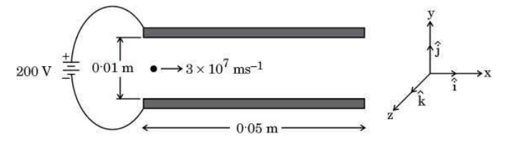
(1) In the region between the plates, the electron moves with an acceleration 𝐚⃗ given by: (A) −(3.5 × 10¹⁵ m s⁻²) k̂ (B) (3.5 × 10¹⁵ m s⁻²) k̂ (C) (3.5 × 10¹³ m s⁻²) î (D) −(3.5 × 10¹³ m s⁻²) î
Correct Answer is Option (B) Formula: Acceleration (a) equals Force divided by mass (m), where Force is charge (q) times Electric Field (E).
Charge: An electron has a negative charge (-1.6 * 10^-19 C
Direction: Since the electron is negative, it accelerates opposite to the electric field, moving upward (+k^).
Calculation: a = (1.6 10^-19 C 2 10^4 V/m) / (9.1 10^-31 kg) = 3.5 * 10^15 m/s^2
(2) The electric field 𝐄⃗in the region between the plates is: (A) ⟮2 × 10² V/m⟯ k̂ (B) −⟮2 × 10² V/m⟯ k̂ (C) ⟮2 × 10⁴ V/m⟯ k̂ (D) −⟮2 × 10⁴ V/m⟯ k̂
(3) Time interval during which an electron moves through the region between the plates is: (A) 9.0 × 10⁻⁹ s (B) 1.67 × 10⁻⁸ s (C) 1.67 × 10⁻⁹ s (D) 2.17 × 10⁻⁹ s
(4) Which one of the following is the path traced by the electron in between the two plates? (A) a (B) b (C) c (D) d
Correct Answer is option (c)
Charge: An electron carries a negative charge.
Force: Negatively charged particles are attracted toward the positive plate and repelled by the negative plate.
Deflection: The electric field between the plates exerts a downward force on the electron, pulling it toward plate A.
Path: Path c is the only trajectory showing downward deflection.
(5) The vertical displacement of the electron which travels through the region between the plates is : (A) 10 mm (B) 4·9 mm (C) 5·9 mm (D) 3·0 mm
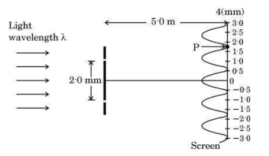
(1) What property of light does this interference experiment demonstrate? (A) Wave nature of light (B) Particle nature of light (C) Transverse nature of light (D) Both wave nature and transverse nature of light
(2) The wavelength of light used in this experiment is: (A) 720 nm (B) 590 nm (C) 480 nm (D) 364 nm
Correct answer is option (c)
From the graph, the fringe width (distance between two consecutive bright fringes) is 1.2 mm.
Fringe width = (wavelength * D) / d
1.2 10^-3 = (wavelength 5.0) / (2.0 * 10^-3)
wavelength = (1.2 10^-3 2.0 10^-3) / 5.0 = 4.8 10^-7 m = 480 nm
(3) The path difference between the two waves meeting at point P, where there is a minimum in the interference pattern is: (A) 8.1 × 10⁻⁷ m (B) 7.2 × 10⁻⁷ m (C) 6.5 × 10⁻⁷ m (D) 6.0 × 10⁻⁷ m
Correct answer is option (B)
Point P is at the second minimum from the center.
Path difference for the second minimum = 1.5 * wavelength
Path difference = 1.5 480 10^-9 m = 720 10^-9 m = 7.2 10^-7 m
(4) The fringe width in the interference pattern formed on the screen is: (A) 1.2 mm (B) 0.2 mm (C) 4.2 mm (D) 6.8 mm
(5) When the experiment is performed in a liquid of refractive index greater than 1, then fringe pattern will : (A) disappear (B) become blurred (C) be widened (D) be compressed
Correct Answer is option (D)
When placed in a liquid, the wavelength of light decreases. Since fringe width is directly proportional to the wavelength, the fringe width decreases, causing the pattern to shrink or compress.
Section B
Two small identical metallic balls having charges q and – 2q are kept far at a separation r. They are brought in contact and then separated at distance r/2 . Compared to the initial force F, they will now :
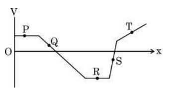
The figure represents the variation of the electric potential V at a point in a region of space as a function of its position along the x-axis. A charged particle will experience the maximum force at :
Four long straight thin wires are held vertically at the corners A, B, C and D of a square of side ‘a’, kept on a table and carry equal current ‘I’. The wire at A carries current in upward direction whereas the current in the remaining wires flows in downward direction. The net magnetic field at the centre of the square will have the magnitude:
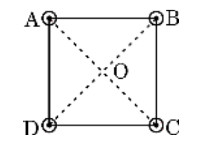
The magnetic field due to a long straight wire at a distance R is B = μ₀I/(2πR). Here, the center of the square is at a distance of a/√2 from each corner wire. The magnitude of the magnetic field due to each wire at the center is therefore μ₀I/(2π * (a/√2)) = μ₀I√2/(2πa). Since wire A has current upward and the others downward, their magnetic fields have directions that combine vectorially. The resultant magnetic field magnitude adds up to μ₀I√2/(πa) and is directed along OB, diagonally opposite to corner B.
The magnetic flux through a loop placed in a magnetic field can be changed by changing:
Magnetic flux depends on the magnetic field strength, the area of the loop, and the angle (orientation) between the magnetic field and the loop. Changing any one or more of these factors will change the magnetic flux. For example, rotating the coil changes the angle, shrinking or stretching changes the area, and changing the magnetic field strength directly affects the flux.
Which of the following statements is not true for electric energy in ac form compared to that in dc form?
The given context states that AC can be easily transformed to different voltages and can travel long distances economically with less energy loss, making production and transmission of AC economical. However, it does not mention that AC is less dangerous than DC. In fact, AC is generally considered more dangerous than DC at the same voltage because of its alternating nature affecting the human body differently. Therefore, the statement 'ac is less dangerous' is not true.
The magnetic field in a plane electromagnetic wave travelling in glass (n = 1.5) is given by Bᵧ = (2 × 10⁻⁷ T) sin (αx + 1.5 × 10¹¹ t) where x is in metres and t is in seconds. The value of α is:
The wave number α is related to the angular frequency ω and the speed of the wave v by α = ω / v. Given that the wave travels in glass with refractive index n = 1.5, the speed of the wave is v = c / n = 3 × 10^8 / 1.5 = 2 × 10^8 m/s. The angular frequency ω is 1.5 × 10^11 rad/s as given in the sine function. Therefore, α = ω / v = (1.5 × 10^11) / (2 × 10^8) = 7.5 × 10^2 m⁻¹. Hence, the correct value of α is 7.5 × 10² m⁻¹.
Light of which of the following colours will have the maximum energy in a photon associated with it ?
Energy of a photon is directly proportional to its frequency and inversely proportional to its wavelength. Among the given colors, blue light has the shortest wavelength (around 450 to 500 nm) and therefore the highest frequency, resulting in the maximum photon energy. Red light has the longest wavelength, followed by yellow and green, so they have lower energy compared to blue light.
Nuclides with the same number of neutrons are called:
Nuclides with the same neutron number N but different atomic number Z are called isotones. According to the context, isotopes have the same atomic number Z but different neutron number, isobars have the same mass number A, and isomers are different states of the same nuclide. Therefore, 'Isotones' is the correct answer for nuclides with the same number of neutrons.
The energy of an electron in an orbit in hydrogen atom is –3.4 eV. Its angular momentum in the orbit will be:
A good diode checked by a multimeter should indicate:
The rms and the average value of an ac voltage V = V₀ sin ωt volt over a cycle respectively will be:
Assertion (A): Induced emf produced in a coil will be more when the magnetic flux linked with the coil is more. Reason (R): Induced emf produced is directly proportional to the magnetic flux.
Assertion (A): In Young’s double-slit experiment, the fringe width for dark and bright fringes is the same. Reason (R): Fringe width is given by β = λD/d, where symbols have their usual meanings.
In Young's double-slit experiment, the fringe width (β) which is the distance between two consecutive bright or dark fringes is given by β = λD/d, where λ is the wavelength of light, D is the distance between the slits and the screen, and d is the distance between the two slits. This means the spacing between bright fringes and dark fringes is equal, hence the fringe width for both dark and bright fringes is the same. Therefore, both the assertion and reason are true, and the reason correctly explains the assertion.
Assertion (A): Energy is released when heavy nuclei undergo fission or light nuclei undergo fusion. Reason (R): For heavy nuclei, binding energy per nucleon increases with increasing Z while for light nuclei, it decreases with increasing Z.
Energy is released in nuclear reactions when nuclei move toward a state of higher binding energy per nucleon. Heavy nuclei release energy by splitting (fission) into smaller nuclei because the binding energy per nucleon increases for these smaller nuclei as compared to the heavy nucleus. Light nuclei release energy by combining (fusion) into heavier nuclei because the binding energy per nucleon increases for heavier nuclei up to iron. However, the Reason (R) is incorrect because for heavy nuclei, binding energy per nucleon actually decreases with increasing atomic number (Z), and for light nuclei, it increases with increasing mass number up to iron, not decreases.
Assertion (A): Photoelectric effect is a spontaneous phenomenon. Reason (R): According to the wave picture of radiation, an electron would take hours/days to absorb sufficient energy to overcome the work function and come out from a metal surface.
Section C
An electric iron rated 2.2 kW, 220 V is operated at 110 V supply. Find:
(i) its resistance, and
(ii) heat produced by it in 10 minutes.
Power rating P = 2.2 kW = 2200 W, Voltage V = 220 V
Using the formula P = V2 / R,
Resistance R = V2 / P = (220)2 / 2200 = 48400 / 2200 = 22 Ω
(ii) Heat produced when operated at 110 V for 10 minutes
When voltage is 110 V, current I = V / R = 110 / 22 = 5 A
Power at 110 V, P' = V * I = 110 * 5 = 550 W
Time t = 10 minutes = 10 * 60 = 600 seconds
Heat produced, H = Power * time = 550 * 600 = 330000 J
So, the heat produced in 10 minutes is 330000 joules or 330 kJ.
A current of 4.0 A flows through a wire of length 1 m and cross-sectional area 1.0 mm², when potential difference of 2 V is applied across its ends.
Calculate the resistivity of the material of the wire.
Current, I = 4.0 A
Length of wire, L = 1 m
Cross-sectional area, A = 1.0 mm² = 1.0 * 10-6 m²
Potential difference, V = 2 V
Using Ohm's law: V = IR => Resistance R = V / I = 2 / 4 = 0.5 ohm
Resistivity, rho = R * A / L = 0.5 * 1.0 * 10-6 / 1 = 0.5 * 10-6 ohm meter
Therefore, the resistivity of the material is 5.0 * 10-7 ohm meter.
A plane circular coil is rotated about its vertical diameter with a constant angular speed ω in a uniform horizontal magnetic field. Initially the plane of the coil is parallel to the magnetic field. Draw plots showing the variation of the following physical quantities as the function of ωt, where t represents time elapsed:
(a) Magnetic flux ϕ linked with the coil, and
(b) emf induced in the coil.
(b) The emf induced in the coil is given by ε = NBA ω sin(ωt). It varies as a sine wave with time, being zero when the flux is maximum and maximum when the flux changes fastest. The plot of induced emf versus ωt is a sine wave starting from zero at ωt = 0.
Thus, magnetic flux and emf vary with ωt as cosine and sine functions respectively, both repeating periodically with rotation.
A tank is filled with a liquid to a height of 12.5 m. The apparent depth of a needle lying at the bottom of the tank is measured to be 9.0 m. Calculate the speed of light in the liquid.
Real depth, d = 12.5 m
Apparent depth, d' = 9.0 m
The refractive index of the liquid, n = real depth / apparent depth = 12.5 / 9.0 = 1.39
The refractive index is also the ratio of speed of light in air (v_air) to speed of light in liquid (v_liquid), so n = v_air / v_liquid
Speed of light in air, v_air = 3.0 * 108 m/s
Therefore, v_liquid = v_air / n = (3.0 * 108) / 1.39 = 2.16 * 108 m/s
Hence, the speed of light in the liquid is 2.16 * 108 meters per second.
Two thin lenses of focal length f₁ and f₂ are placed in contact with each other coaxially. Prove that the focal length f of the combination is given by f = (f₁f₂)/(f₁ + f₂)
Rearranging, 1/f = (f₁ + f₂) / (f₁ * f₂).
Taking the reciprocal, f = (f₁ * f₂) / (f₁ + f₂).
This shows that the focal length of the combination of two thin lenses in contact is given by the product of their focal lengths divided by their sum.
Suppose a pure Si crystal has 5 × 10²⁸ atoms per m³. It is doped with 5 × 10²² atoms per m³ of Arsenic. Calculate the majority and minority carrier concentration in the doped silicon. (Given: nᵢ = 1.5 × 10¹⁶ m⁻³)
Step 1: Since Arsenic is pentavalent, it donates electrons, so electrons are majority carriers.
Step 2: Majority carrier concentration (electrons), n = dopant concentration ND = 5 * 1022 m-3.
Step 3: Minority carrier concentration (holes), p = ni2 / n = (1.5 * 1016)2 / (5 * 1022) = 4.5 * 109 m-3.
Conclusion: Majority carriers (electrons) = 5 * 1022 m-3, Minority carriers (holes) = 4.5 * 109 m-3.
Section D
Two parallel plate capacitors X and Y are connected in series to a 6 V battery. They have the same plate area and same plate separation but capacitor X has air between its plates, whereas capacitor Y contains a material of dielectric constant 4.
(a) Calculate the capacitances of X and Y, if the equivalent capacitance of the combination is 4 μF.
(b) Calculate the potential difference across the plates of X and Y.
Since X has air and Y has dielectric constant k = 4, we have C_Y = k * C_X = 4C_X.
Substitute into the formula: 1/4 = 1/C_X + 1/4C_X = (1 + 1/4) / C_X = 5/4C_X.
So, 1/4 = 5/(4C_X) => C_X = 5 μF.
Then, C_Y = 4 * 5 = 20 μF.
(b) In series connection, the charge Q on both capacitors is the same and Q = C_eq * V = 4 μF * 6 V = 24 μC.
Potential difference across X, V_X = Q/C_X = 24 μC / 5 μF = 4.8 V.
Potential difference across Y, V_Y = Q/C_Y = 24 μC / 20 μF = 1.2 V.
Hence, the capacitances are C_X = 5 μF, C_Y = 20 μF, and the potential differences are V_X = 4.8 V, V_Y = 1.2 V.
Write the expression for the magnetic field due to a current element in vector form. Consider a 1 cm segment of a wire, centered at the origin, carrying a current of 10 A in positive x-direction. Calculate the magnetic field 𝐁⃗ at a point (1 m, 1 m, 0).
Given:
Length of current element, d
Current, I = 10 A
Point P at (1 m, 1 m, 0), so position vector r = 1 i_hat + 1 j_hat + 0 k_hat
Distance r = sqrt(1^2 + 1^2) = sqrt(2) m
Unit vector r^ = (1/sqrt(2)) i_hat + (1/sqrt(2)) j_hat
Calculate d
d
Now, dB = (mu_0 / (4 * pi)) * (I * (d
= 10^-7 * (0.1 / (2.828)) k_hat = 10^-7 * 0.0354 k_hat = 3.54 * 10^-9 k_hat Tesla
Therefore, the magnetic field vector at point P is B = 3.54 * 10^-9 k_hat Tesla, which is directed along positive z-direction perpendicular to the plane containing the wire and point P.
A long solenoid of length L and radius r₁ having N₁ turns is surrounded symmetrically by a coil of radius (r₂ > r₁) having N₂ turns (N₂ << N₁) around its mid-point. Derive an expression for the mutual inductance of solenoid and coil. Is M₁₂ = M₂₁ valid in this case?
(b) Similarly, if a current I₂ flows in the surrounding coil, flux linked with the solenoid will be negligible because the solenoid is inside and its cross-sectional area is smaller. Hence, the mutual inductance M₁₂ = ΔΦ₁ / I₂ is also equal to M₂₁ by the reciprocity theorem.
(c) Therefore, M₁₂ = M₂₁ = μ₀ N₁ N₂ π r₁ 2 / L. This equality is always valid due to the law of mutual induction, regardless of the difference in radius or number of turns, as long as the magnetic coupling is linear and without energy loss.
What is displacement current (i_d)? Considering the case of charging of a capacitor, show that i_d = ε₀ (dΦ_E/dt). What is the value of i_d for a conductor across which a constant voltage is applied?
(b) For a capacitor being charged, the electric flux Φ_E between the plates changes with time. Displacement current i_d is given by i_d = ε₀ (dΦ_E/dt), where ε₀ is the permittivity of free space and dΦ_E/dt is the rate of change of electric flux.
(c) If a constant voltage is applied across a conductor, the electric field does not change with time, so dΦ_E/dt = 0. Therefore, the displacement current i_d in a conductor with constant voltage is zero.
(i) Write any two features of nuclear forces.
(ii) If both the number of protons and the neutrons are conserved in each nuclear reaction, in what way is mass converted into energy (or vice versa) in a nuclear reaction? Explain.
1. Nuclear forces are very strong but act only at very short distances, typically within the nucleus.
2. These forces are attractive and act between all nucleons, that is, between protons and protons, neutrons and neutrons, and protons and neutrons.
(ii) Even though the number of protons and neutrons are conserved in a nuclear reaction, the total mass of the products may be slightly different from the total mass of the reactants. This difference in mass is called the mass defect. According to Einstein's equation E = mc2, this small loss or gain in mass is converted into energy or vice versa during the nuclear reaction. This is why a nuclear reaction can release or absorb a large amount of energy though the number of nucleons remains unchanged.
(i) Draw the number of scattered particles versus the scattering angle graph for scattering of alpha particles by a thin foil. Write two important conclusions that can be drawn from this plot.
(ii) If Bohr's quantization postulate (angular momentum = nh/2π) is a basic law of nature, it should be equally valid for the case of planetary motion also. Why, then, do we never speak of quantization of orbits of planets around the Sun? Explain.
1. Most alpha particles pass straight through the foil with little deflection, showing the atom is mostly empty space.
2. A few particles are deflected at large angles due to the presence of a small, dense, positively charged nucleus.
(ii) Although Bohr's quantization rule applies well to electrons in atoms, it is not observed in planetary motion because the angular momentum of planets is extremely large compared to Planck's constant h. The quantized levels would be so close that they appear continuous, making quantization effects negligible in planetary scales.
Photoemission of electrons occurs from a metal (ϕ₀ = 1.96 eV) when light of frequency 6.4 × 10¹⁴ Hz is incident on it. Calculate:
(a) Energy of a photon in the incident light,
(b) The maximum kinetic energy of the emitted electrons, and
(c) The stopping potential.
E = 6.63 * 10-34 * 6.4 * 1014 = 4.2432 * 10-19 J.
Convert to eV: E = (4.2432 * 10-19)/(1.6 * 10-19) = 2.65 eV.
(b) Maximum kinetic energy Kmax = E - ϕ₀ = 2.65 eV - 1.96 eV = 0.69 eV.
(c) Stopping potential V₀ = Kmax / e = 0.69 V.
Therefore, the energy of the photon is 2.65 eV, the maximum kinetic energy of emitted electrons is 0.69 eV and the stopping potential is 0.69 V.
Draw a circuit diagram of a full-wave rectifier using p-n junction diodes. Explain its working and show the input-output waveforms.
Working: During the positive half cycle of the input AC, diode D1 becomes forward biased and conducts, while diode D2 is reverse biased and does not conduct. So current flows through D1 to the load in one direction.
During the negative half cycle, diode D2 becomes forward biased and conducts, while diode D1 is reverse biased. Current flows through D2 to the load in the same direction as before.
This way, both halves of the AC input produce current flowing in the same direction through the load, resulting in full-wave rectification.
Input-Output Waveforms: The input waveform is sinusoidal AC. The output waveform is a pulsating DC consisting of positive half sine pulses for both the positive and negative half cycles of the input AC, with no negative half cycles.
This increases the average output voltage and efficiency compared to a half-wave rectifier.
Section E
(i) Derive the condition for which a Wheatstone Bridge is balanced.
(ii) Determine the current in 3 Ω branch of a Wheatstone Bridge in the circuit shown in the figure.
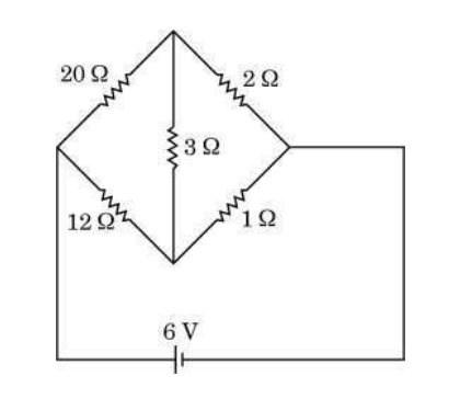
A Wheatstone Bridge has four resistors R1, R2, R3, and R4 arranged in a diamond shape with a galvanometer connected between the middle nodes.
When no current flows through the galvanometer, the bridge is said to be balanced.
This means the potential difference between the middle points is zero.
By applying Kirchhoff's Voltage Law in the two loops, we get the relation:
R1/R2 = R3/R4
This is the balance condition and can be used to determine the unknown resistance if the other three resistances are known.
(ii) Determining the current in the 3 Ω branch:
Consider the given Wheatstone Bridge circuit with known resistances and an applied voltage.
If the bridge is not balanced, current flows through the galvanometer branch and all branches.
This current can be found by applying Kirchhoff's laws:
1. Assign currents to each branch.
2. Write Kirchhoff's Current Law at junctions.
3. Write Kirchhoff's Voltage Law in loops.
4. Solve the simultaneous equations for the current in the 3 Ω branch.
Without the specific values of other resistors and voltage, we cannot find a numerical value here.
With the given circuit values, you can calculate the current by substituting and solving the equations accordingly.
Note: If the bridge is balanced, the current in the 3 Ω branch (assuming it is the galvanometer branch) is zero.
(i) Consider a cylindrical conductor of length l and area of cross-section A. Current I is maintained in the conductor and electrons drift with velocity v_d(|𝐯⃗_d| = e|𝐄⃗ |/m τ), (where symbols have their usual meanings). Show that the conductivity σ of the material of the conductor is given by
σ = ne²/mτ.
(ii) The resistance of a metal wire at 20°C is 1.05 Ω and at 100°C is 1.38 Ω. Determine the temperature coefficient of resistivity of this metal.
Current density J = I/A = ne v_d, where n is number density of electrons.
Substitute v_d = eE/mτ, so J = ne * (eE/mτ) = (ne²/mτ) * E.
By Ohm's law, J = σE, so conductivity σ = ne²/mτ.
(ii) Resistance at 20°C, R₁ = 1.05 Ω; Resistance at 100°C, R₂ = 1.38 Ω.
We know R = ρ * l/A, so resistivity ρ is proportional to resistance.
Temperature coefficient of resistivity α is defined as α = (R₂ - R₁) / (R₁ * (T₂ - T₁)).
Substituting values: α = (1.38 - 1.05) / (1.05 * (100 - 20)) = 0.33 / (1.05 * 80) = 0.33 / 84 = 0.00393 per deg C.
Therefore, the temperature coefficient of resistivity of the metal is approximately 0.00393 per degree Celsius.
(i) A rectangular loop of sides a and b carrying current I is placed in a magnetic field 𝐁⃗ such that its area vector 𝐀⃗ makes an angle θ with 𝐁⃗. With the help of a suitable diagram, show that the torque τ(vector) acting on the loop is given by τ(vector) = 𝐦⃗× 𝐁⃗, where m(vector) (= I 𝐀⃗) is the magnetic dipole moment of the loop.
(ii) A circular coil of 100 turns and radius (10/√π) cm carrying current of 5.0 A is suspended vertically in a uniform horizontal magnetic field of 2.0 T. The field makes an angle 30° with the normal to the coil. Calculate:
(a) the magnetic dipole moment of the coil, and
(b) the magnitude of the counter torque that must be applied to prevent the coil from turning.
(ii)(a) Magnetic dipole moment m of the coil is given by m = N I A, where N = 100 turns, I = 5.0 A, and A = π r2. The radius r = 10/√π cm = 0.10/√π m. So,
A = π (0.10/√π)2 = π * (0.10)2 / π = 0.01 m2.
Therefore, m = 100 * 5.0 * 0.01 = 5.0 A·m2.
(ii)(b) The torque τ experienced by the coil is τ = m B sinθ, where θ = 30°, B = 2.0 T.
Substituting values,
τ = 5.0 * 2.0 * sin 30° = 10 * 0.5 = 5.0 N·m.
This is the magnitude of the counter torque needed to keep the coil from turning against the magnetic torque.
(i) Derive an expression for the force 𝐅⃗ acting on a conductor of length L and area of cross-section A carrying current I and placed in a magnetic field 𝐁⃗ .
(ii) A part of a wire carrying 2.0 A current and bent at 90° at two points is placed in a region of uniform magnetic field 𝐁⃗ = −(0.50 T) k̂, as shown in the figure. Calculate the magnitude of the net force acting on the wire.
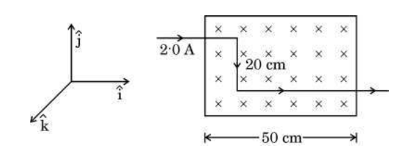
(ii) Given: current I = 2.0 A, magnetic field 𝐁⃗ = -0.50 T k̂, wire has two bends at 90 degrees forming three segments with current directions given by the bends. Since the magnetic field is along -k̂ direction, and the wire segments are oriented along x̂ and ŷ due to 90° bends, the force on each straight segment is F = I L B sin θ. Here, sin θ = 1 because the current direction is perpendicular to magnetic field for each segment. Force on each segment has direction given by right-hand rule (𝐋⃗ × 𝐁⃗). Considering the geometry and directions, the forces on segments in x̂ and ŷ directions are perpendicular, so the net force is the vector sum. If the lengths of the straight segments are equal or known, sum their forces vectorially to find net force magnitude. Without lengths specified, assuming equal length L, the net force magnitude is F_net = I B L sqrt(2) due to the two perpendicular forces of same magnitude. Substituting values with L in meters will yield the numerical answer. Thus, the force depends on current, magnetic field, length, and relative directions.
(i) A parallel beam of monochromatic light falls normally on a single slit of width ‘a’ and a diffraction pattern is observed on a screen placed at distance D from the slits. Explain :
(I) the formation of maxima and minima in the diffraction pattern, and
(II) why the maxima go on becoming weaker and weaker with its increasing number (n).
(ii) Write any two points of difference between interference pattern due to double-slit and diffraction pattern due to single-slit.
(b) The intensity of maxima decreases as the order number 'n' increases because the path difference between light from different parts of the slit increases, resulting in less perfect constructive interference. Therefore, higher order maxima become weaker and less bright.
(ii) Differences between interference pattern due to double-slit and diffraction pattern due to single-slit:
1. Interference fringes from double-slit are equally spaced bright and dark bands, whereas single-slit diffraction pattern has a central bright maximum much wider than the others, with successive maxima weaker and narrower.
2. Double-slit interference occurs due to superposition of light from two coherent sources, whereas single-slit diffraction occurs due to interference of light waves originating from different parts of the same slit.
(i) With the help of a ray diagram, describe the construction and working of a compound microscope.
(ii) (I) The real image of an object placed between f and 2f from a convex lens can be seen on a screen placed at the image location. If the screen is removed, is the image still there ? Explain.
(II) Plane and convex mirrors produce virtual images of objects. Can they produce real images under some circumstances ? Explain.
A compound microscope consists of two convex lenses: the objective lens and the eyepiece lens fixed at a short distance inside a tube. The objective lens is placed close to the object to be observed, which is just beyond its focal length. The eyepiece lens is nearest to the eye.
Working:
1. The objective lens forms a real, inverted, and magnified image of the object inside the tube at a position beyond its focal length.
2. This image acts as the object for the eyepiece lens.
3. The eyepiece lens further magnifies this image by forming a virtual, enlarged, and erect image that can be seen by the eye.
4. The final image is highly magnified and can be used to observe fine details.
(ii)(a) Yes, the image is still there even if the screen is removed. The real image formed by the convex lens is a convergence of light rays at a point in space. The screen merely helps us to see the image by catching the light rays. Removing the screen does not destroy the image; it can still be seen by placing a surface or by observation from that point.
(ii)(b) Plane and convex mirrors generally produce virtual images because they cause light rays to diverge, making images appear behind the mirror. However, under normal circumstances, they cannot produce real images because they do not converge light rays in front of the mirror. Therefore, plane and convex mirrors do not produce real images under any usual conditions.
Other Years — Physics