SOLUTIONS
2026 BOARD EXAM
CBSE Class 12 PCM Physics Board Paper 2026 — Set 4 Solutions
2026
Physics
Class 12 PCM
CBSE EXAMINATION PAPER-2026
PHYSICS
(Solved)
General Instructions :
Read the following instructions carefully and follow them :
- This question paper contains 38 questions. All questions are compulsory.
- This question paper is divided into 5 sections.
- Section A – questions number 1 to 2 are case based questions
- Section B – questions number 3 to 18 are multiple choice questions
- Section C – questions number 19 to 24 are very short answer
- Section D – questions number 25 to 32 are short answer
- Section E – questions number 33 to 38 are long answer
- There is no overall choice given in the question paper. However, an internal choice has been provided in few questions.
- Use of calculator is NOT allowed.
Section A
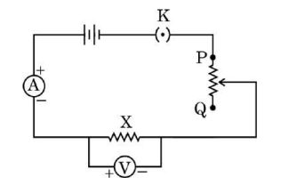
(1) Error in the value of X obtained from different sets of voltmeter and ammeter readings, is : (A) due to error in voltmeter reading only (B) due to error in ammeter reading only (C) equal to the sum of error in voltmeter reading and error in ammeter reading (D) equal to error in voltmeter reading divided by the error in ammeter reading
Correct Answer is Option (C)
Reason: The resistance is calculated using the formula (X = V/I).
According to the rules of error propagation, the relative or percentage error in a quotient is the sum of the relative errors of the individual quantities.
Therefore, the error depends on the sum of errors from both the voltmeter and the ammeter.
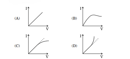
(2) If resistor X were made of manganin and readings for V and I are taken without switching off the circuit, the graph between V and I will be as :
 [1 Mark]
Correct Answer is Option (A)
Reason: Manganin is an alloy with a negligible temperature coefficient of resistance.
Its resistance remains virtually constant even if the circuit stays on and heats up.
Since resistance stays constant, it strictly obeys Ohm's Law (V = IR), resulting in a straight-line graph passing through the origin.
(3) If the movable end of rheostat is moved towards P, then : (A) reading in ammeter decreases and reading in voltmeter increases (B) readings in both voltmeter and ammeter increase (C) reading in ammeter increases and reading in voltmeter decreases (D) readings in both voltmeter and ammeter decrease
Correct Answer is Option (B)
Reason: Moving the rheostat slider towards P shortens the effective length of the resistance wire in the circuit.
Shorter length reduces the circuit's total resistance.
Lower resistance increases the total current flowing through the circuit, raising the ammeter reading.
Since current increases, the potential difference across resistor X (V = IR) also increases, raising the voltmeter reading
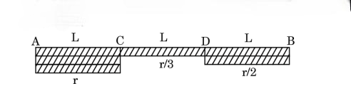
(4) Suppose the unknown resistance X is replaced by a wire made of the same metal. This wire consists of three parts, of the same length L but has radii r, r/3 and r/2 as shown in the figure. For a particular setting of the rheostat, let v₁, v₂ and v₃ be the value of drift velocities in parts AC, CD and DB. Then: (A) v₁ > v₂ > v₃ (B) v₂ > v₃ > v₁ (C) v₃ > v₂ > v₁ (D) v₁ = v₂ = v₃
 [1 Mark]
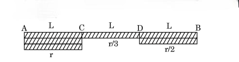
(5) Consider the same wire, as shown in figure in question (iv) (a) connected in place of X. For a particular setting of rheostat, let E1 , E2 and E3 be the value of electric fields in part AC, CD and DB. Then : (A) E₁ = E₂ = E₃ (B) E₃ > E₂ > E₁ (C) E₂ > E₃ > E₁ (D) E₁ > E₂ > E₃
 [1 Mark]
Correct Answer is Option (B)
Reason: For a wire carrying a uniform current in series, the electric field is given by (E = I /σ.A),where σ is the conductivity.
This means the electric field is inversely proportional to the cross-sectional area, and thus inversely proportional to the square of the radius (E∝ 1/ʳ²)
Since the smallest radius is at CD (r/3) and the largest is at AC (r), the electric field strength follows the reverse order: (E_2 > E_3 > E_1).
(1) The images formed by the objective lens and the eyepiece are respectively: (A) virtual, real (B) real, virtual (C) virtual, virtual (D) real, real
(2) The magnification produced by the telescope does not depend upon the: (A) colour of light (B) focal length of objective lens (C) focal length of eyepiece (D) apertures of objective lens and eyepiece
Correct Answer is Option (D)
The magnifying power of a telescope depends purely on the focal lengths of the lenses and the color (wavelength) of light. The aperture (diameter) of the lenses only determines the light-gathering capacity and brightness of the image, not its geometric magnification.
(3) Which of the following statements is not correct for this telescope? (A) The focal length of objective lens (fₒ) is larger than the focal length of eyepiece (fₑ) (B) Its magnifying power can be increased by increasing the focal length of objective lens (fₒ) (C) The distance between two lenses is more than (fₒ + fₑ) (D) The magnifying power can be decreased by increasing the focal length of eyepiece
(4) An astronomical telescope has objective lens and eyepiece of focal lengths 80 cm and 4 cm respectively. To view the image in normal adjustment, the lenses must be separated by a distance of : (A) 84 cm (B) 76 cm (C) 20 cm (D) 320 cm
(5) Consider the telescope described in question (iv) (a). Its magnifying power in normal adjustment will be : (A) 320 (B) 84 (C) 76 (D) 20
Correct Answer is Option (D)
The formula for the magnifying power of an astronomical telescope in normal adjustment is:
Magnification = fo / fe
Magnification = 80 / 4 = 20
Section B
Two wires of same length and same area of cross-section but made of different material of resistivities ρ₁ and ρ₂ are connected in series. The equivalent resistivity of the combination is:
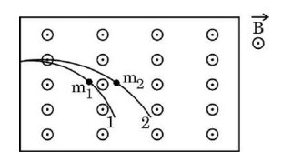
Two particles of masses m₁ and m₂ having charges q₁ and q₂ respectively are projected with the same velocity in a region of uniform magnetic field 𝐁⃗ pointing vertically upward. If they describe circular paths as shown in the figure, one may conclude that:
An electron moves around the nucleus in a circular orbit of radius r and makes n revolutions per second. The value of equivalent current in the orbit is:
Current is defined as charge passing through a point per unit time. Here, the electron (charge e) completes n revolutions per second, so the charge passes the same point n times in one second. Therefore, the equivalent current I = n × e = ne.
The dimensions of the rate of change of magnetic flux are:
Magnetic flux (φ_B) has dimensions [M L^2 T^-2 A^-1]. The rate of change of magnetic flux with respect to time introduces an extra factor of T^-1, as rate of change with time involves dividing by time. Therefore, the dimensions of the rate of change of magnetic flux are [M L^2 T^-3 A^-1].
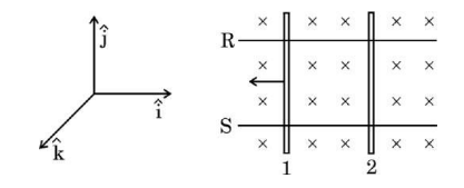
Two identical conductors 1 and 2 are placed on two frictionless conducting rails R and S in a uniform magnetic field directed vertically downward into the plane of the page. If conductor 1 is moved with a constant velocity in the direction as shown in figure, the force on conductor 2 will be along:
An ac voltage is given as V = 14 sin (314t) V. The average and the effective value of the voltage (in V) over a cycle are respectively:
For an AC voltage V = Vmax sin(ωt), the average voltage over one complete cycle is zero because the positive and negative halves cancel out. The effective or RMS value is Vmax / √2. Given Vmax = 14 V, the RMS voltage is 14/√2 ≈ 10 V. Hence, the average is 0 V and the effective value is 10 V.
The ratio of amplitude of electric field to the amplitude of the magnetic field associated with an electromagnetic wave propagating in glass (n = 1.5) is:
While studying photoelectric emission from a given surface, the wavelength of the incident radiation is changed from 600 nm to 400 nm, keeping the intensity of radiation the same. Then:
The cut-off potential (or stopping potential) depends on the frequency (or wavelength) of the incident radiation and is related to the maximum kinetic energy of emitted electrons. When the wavelength decreases from 600 nm to 400 nm, the frequency increases, leading to greater kinetic energy of photoelectrons. Thus, the cut-off potential increases. Since intensity is kept constant, the saturation current, which depends on the intensity, remains unchanged. Hence, the correct answer is that the cut-off potential will increase.
Radiation of wavelength 331 nm irradiates the following metals: Which of the following statements is correct?
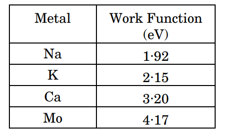
According to the context, alkali metals such as sodium (Na) and potassium (K) can show photoelectric emission even with visible light due to their low work function. Radiation with wavelength 331 nm (which is in the ultraviolet region) has higher energy and can thus eject photoelectrons from metals with moderate work functions. Molybdenum (Mo), being a transition metal, has a higher work function and may not exhibit photoelectric emission at this wavelength. Therefore, only Mo will not show photoelectric emission under 331 nm radiation.
The kinetic energy of a charged particle is increased to four times of its initial value. The de Broglie wavelength associated with the particle will:
The de Broglie wavelength λ is related to the momentum p of a particle by λ = h / p, where h is Planck's constant. Momentum p is related to kinetic energy KE by p = sqrt(2mKE). When the kinetic energy is increased to four times, KE becomes 4KE. Therefore, the momentum becomes p' = sqrt(2m × 4KE) = 2 × sqrt(2mKE) = 2p. Since λ' = h / p' = h / (2p) = λ / 2, the de Broglie wavelength decreases to half (50%) of its initial value.
In a reversed-biased p-n junction diode, the applied voltage mostly drops across:
In a reverse biased p-n junction diode, the positive terminal of the battery is connected to the n-region and the negative terminal to the p-region. This widens the depletion region, which has very high resistance compared to the p-region and n-region. As a result, most of the applied voltage drops across the depletion region, while the voltage drop across the p-region and n-region is negligible.
Assertion (A): When a ferromagnetic substance is heated to high temperature it becomes paramagnetic in nature. Reason (R): The disappearance of magnetisation of a ferromagnet is abrupt and not gradual.
The assertion is correct because a ferromagnetic substance becomes paramagnetic when heated to a sufficiently high temperature (called the Curie temperature). However, the reason is incorrect because the disappearance of magnetisation in a ferromagnet with increase in temperature is gradual, not abrupt. The domain structure disintegrates gradually with temperature leading to a gradual loss of magnetisation.
Assertion (A): When a convex lens made of glass is immersed in water, its converging power increases. Reason (R): The focal length of a lens depends only on the radii of curvature of its two faces.
When a convex lens made of glass is immersed in water, its focal length increases because the refractive index difference between the lens and the surrounding medium decreases. Hence, the converging power (which is inversely proportional to focal length) actually decreases, not increases. Therefore, the assertion that converging power increases is false. Also, the focal length of the lens depends not only on the radii of curvature of its faces but also on the refractive indices of the lens material and the surrounding medium. So, the reason given is false.
Section C
An electric dipole consists of two point charges +1 μC and –1 μC, held 10 cm apart. It is subjected to a uniform electric field of 100 N/C. Calculate the amount of work done in turning the dipole from its position of stable equilibrium to the position of unstable equilibrium, in the field.
The dipole moment p = q * d = 1 * 10^-6 * 0.1 = 1 * 10^-7 C m.
The work done W in rotating the dipole from stable equilibrium (θ = 0 deg) to unstable equilibrium (θ = 180 deg) is W = pE(cos θ_initial - cos θ_final).
Therefore, W = 1 * 10^-7 * 100 * (cos 0 deg - cos 180 deg) = 1 * 10^-5 * (1 - (-1)) = 2 * 10^-5 Joules.
Answer: The work done is 2 * 10^-5 Joules.
State Huygens principle. How did Huygens justify the absence of the backward wave on a spherical wavefront?
(b) Justification for absence of backward wave: Huygens assumed that the amplitude of these secondary wavelets is maximum in the forward direction and zero in the backward direction. This ad hoc assumption explained why the backward wave is not observed. Although this assumption is not fully satisfactory, the absence of the backward wave is properly justified by more rigorous wave theories.
In a single-slit diffraction experiment, light of wavelength λ illuminates the slit of width ‘a’. The diffraction pattern is observed on a screen kept at distance D from the slits.
(i) Depict variation in intensity in the fringe pattern with the angular position of the fringes.
(ii) How is the linear width of central maximum affected when separation between the slit and the screen is decreased?
(ii) The linear width of the central maximum on the screen is given by 2Dλ/a. When the distance D between the slit and screen decreases, the linear width of the central maximum decreases proportionally because it is directly proportional to D.
A small bulb is placed at the bottom of a tank, containing a transparent liquid of refractive index √2, to a depth of 1 m. Calculate the area of the surface of the liquid through which light from the bulb emerges.
Step 1: The critical angle, C = sin-1(1/n) = sin-1(1/sqrt(2)) = 45 deg.
Step 2: Light rays inside the liquid make a cone with half angle C at the bulb.
Step 3: Radius of the circular area on the surface, R = d * tan C = 1 * tan 45 = 1 m.
Step 4: Area of the surface, A = pi * R2 = 3.14 * 12 = 3.14 m2.
Answer: The area of the surface of the liquid through which light emerges is 3.14 m2.
Draw the graph showing the variation of number of scattered alpha particles (N) detected with scattering angle (θ) in Geiger–Marsden experiment. Infer two conclusions from the graph.
(b) Most alpha particles scatter at very small angles close to 0°, with N very high near 0°.
(c) Number of scattered particles decreases drastically as θ increases and very few particles are scattered at angles near 180°.
(d) Conclusions:
1. Most alpha particles pass through the foil undeflected meaning atoms are mostly empty space.
2. A small number of alpha particles scatter at large angles, indicating presence of a small dense positively charged nucleus inside atom.
The hole concentration in an intrinsic semiconductor is 5 × 10⁸ m⁻³. When it is doped with certain impurity, the electron concentration becomes 4 × 10¹² m⁻³. Find the new value of the hole concentration. Also identify the type of new semiconductor formed after doping.
Step 1: In intrinsic semiconductor, ni = pi = 5 * 108 m-3.
Step 2: For doped semiconductor, n * p = ni2. So, p = ni2 / n = (5 * 108)2 / (4 * 1012) = 25 * 1016 / 4 * 1012 = 6.25 * 104 m-3.
Step 3: Since electron concentration is much greater than hole concentration, majority carriers are electrons. So, the semiconductor is n-type after doping.
Section D
State Kirchhoff’s rules. Using these rules, find the current flowing through branch FC in the given circuit.
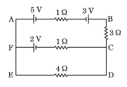
Kirchhoff's First Rule (Junction Rule): The algebraic sum of currents meeting at a junction is zero. This means the sum of currents entering a junction equals the sum of currents leaving it.
Kirchhoff's Second Rule (Loop Rule): The algebraic sum of the products of currents and resistances and the emf’s in any closed loop of a circuit is zero.
(b) Finding Current through Branch FC:
1. Assign current variables to each branch including branch FC.
2. Apply Kirchhoff's junction rule at suitable nodes to express currents relation.
3. Apply Kirchhoff's loop rule to the independent loops involving branch FC to form equations with currents.
4. Solve the simultaneous equations obtained to find the current through branch FC.
5. The direction of current assumed initially is considered positive if the final value is positive; if negative, the current flows opposite.
Thus, by systematically applying Kirchhoff's rules and solving the equations, the current in branch FC can be determined accurately.
The figure given below shows three straight long parallel conductors ①, ② and ③ kept in x-y plane, carrying currents 2I, I and 3I respectively as shown in figure.
Find the magnitude and direction of:
(i) net magnetic field at a point on conductor ① and
(ii) net magnetic force acting on unit length of conductor ①, due to conductors ② and ③.
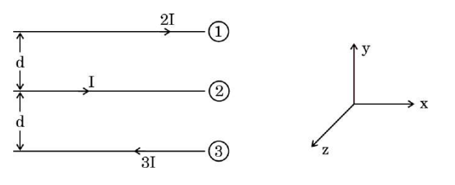
Magnetic field due to conductor ② at ①: B2 = (mu0 * I) / (2 * pi * r12), direction given by right-hand rule.
Magnetic field due to conductor ③ at ①: B3 = (mu0 * 3I) / (2 * pi * r13), direction also by right-hand rule.
The directions of B2 and B3 depend on current directions; sum vectorially to get net B.
(ii) The force per unit length on conductor ① due to conductor ② is F12/L = (mu0 * 2I * I) / (2 * pi * r12), attractive or repulsive depending on current directions.
Similarly, force per unit length on ① due to ③ is F13/L = (mu0 * 2I * 3I) / (2 * pi * r13).
Net force per unit length on ① is vector sum of F12/L and F13/L. Direction is along line joining the conductors, given by attraction if currents are in same direction, repulsion if opposite.
Thus, by calculating individual magnetic fields and forces using the formula and summing vectorially considering directions, we get the required net magnetic field and force on conductor ①.
A rectangular loop of sides l and b and resistance ‘R’ is kept in a region in which the magnetic field varies as B = B₀ sin ωt.
(i) Derive the expression for the emf induced in the loop.
(ii) Find the effective value of current that flows in the loop.
The magnetic flux Φ through the rectangular loop is given by Φ = B A, where A = l * b is the area of the loop.
Given, B = B₀ sin ωt, so Φ = B₀ sin ωt * l * b.
According to Faraday’s law of electromagnetic induction, emf ε = − dΦ/dt.
Calculating derivative, dΦ/dt = B₀ l b ω cos ωt.
So, emf, ε = − B₀ l b ω cos ωt.
(ii) Effective value of current:
The induced current I = emf / R = (− B₀ l b ω cos ωt) / R.
The effective value or RMS value of current Ieff is obtained by taking RMS of cos ωt which is 1 / sqrt(2).
Hence, Ieff = (B₀ l b ω) / (R sqrt(2)).
The figure given below shows a square-shaped loop MNOP of side 25 cm placed horizontally in a uniform magnetic field B(vector) directed vertically downward. The position of the loop at t = 0 s is as shown in figure. The loop is pulled with a constant velocity of 25 cm/s till it goes out of the field.
(a) What will be the direction of the induced current in the loop as it goes out of the field? For how long would the current in the loop persist?
(b) Plot graphs showing the variation of magnetic flux and magnitude of induced emf as a function of time.
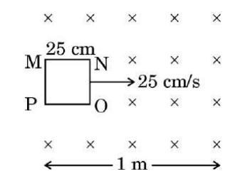
The current persists only while the loop is partially in the magnetic field, i.e., while the flux changes. The loop side is 25 cm and velocity is 25 cm/s, so it takes time t = side/velocity = 25 cm / 25 cm/s = 1 second. Thus, the induced current will last for 1 second.
(b) The magnetic flux decreases linearly from its initial value to zero in 1 second as the loop moves out. So, the flux vs time graph is a straight line decreasing from maximum flux at t=0 to zero at t=1 s.
The magnitude of induced emf is the rate of change of flux, which is constant because flux decreases uniformly. Hence, the emf vs time graph is a constant horizontal line during the 1 second and zero afterwards.
The graphs are:
- Magnetic flux vs time: straight line decreasing from maximum flux to zero over 1 second
- Induced emf vs time: constant nonzero value for 1 second, then zero
This shows the induced current exists only during the time flux changes due to the loop moving out of the field.
What are infrared waves ? Why are these waves referred to as ‘heat waves’ ? Give any two uses of these waves.
(a) Infrared waves are electromagnetic waves with frequencies lower than visible light and lie adjacent to the visible spectrum's low-frequency or long-wavelength end. They are produced by hot bodies and molecules.
(b) These waves are called ‘heat waves’ because many molecules, especially water molecules in materials, absorb infrared waves easily. This absorption increases the thermal motion of molecules, raising the temperature of the substance and its surroundings.
(c) Two uses of infrared waves are:
1. Infrared lamps are used in physical therapy to provide heat to injured muscles and tissues.
2. They are used in night vision devices to detect heat emitted by objects in darkness.
(a) Explain how the dual aspect of matter is evident in the de Broglie relation.
(b) Radiation of wavelength λ is incident on a photosensitive surface. Find the de Broglie wavelength of electrons emitted from the surface. Assume that the work function of the surface is negligible.
(b) Given radiation of wavelength λ incident on a photosensitive surface with negligible work function, the energy of the incident photon is E = hc / λ. Since work function is negligible, this photon energy converts entirely into kinetic energy of the emitted electron.
Therefore, K.E. = E = hc / λ = (1 / 2) m v2
Momentum of electron p = m v = sqrt(2 m K.E.) = sqrt(2 m (hc / λ))
De Broglie wavelength of emitted electron λe = h / p = h / sqrt(2 m hc / λ) = sqrt(λ h / 2 m c)
This is the expression for the de Broglie wavelength of electrons emitted when radiation of wavelength λ falls on a surface with negligible work function.
In the nuclear reaction:
²₁H + ²₁H → ᴬ₂X + ¹₀n
(a) Find the value of A.
(b) Calculate the amount of energy released in the reaction.
Given: m(²₁H) = 2.014102 u, m(ᴬ₂X) = 3.016049 u,
m(¹₀n) = 1.008665 u, 1 u = 931.5 MeV/c²
(b) To calculate the energy released, first find the mass defect: mass defect = mass of reactants - mass of products = (2.014102 + 2.014102) u - (3.016049 + 1.008665) u = 4.028204 u - 4.024714 u = 0.00349 u.
Energy released, E = mass defect * 931.5 MeV/u = 0.00349 * 931.5 = 3.25 MeV.
Final answers: (a) A = 3
(b) Energy released = 3.25 MeV
With the help of a circuit diagram, explain the working of a full wave rectifier. Depict the input and output waveforms.
(a) Circuit Diagram: It consists of a center-tapped transformer and two diodes connected such that each diode conducts during alternate half cycles of the AC input.
(b) Working: During the positive half cycle of AC, diode D1 conducts and D2 is reverse biased, allowing current through the load in one direction.
During the negative half cycle, diode D2 conducts and D1 is reverse biased, again allowing current in the same direction through the load.
This way, both half cycles produce current in the same direction.
(c) Waveforms: The input waveform is a sinusoidal AC voltage.
The output voltage across the load is a series of positive pulses corresponding to both half cycles, producing a pulsating DC voltage.
This pulsating DC can be filtered to get smooth DC voltage.
Section E
(i) Define refractive index of a medium in terms of speed of light.
(ii) Derive the relation for the refractive index (μ) of a prism in terms of angle of minimum deviation (δₘ) and angle of prism (A).
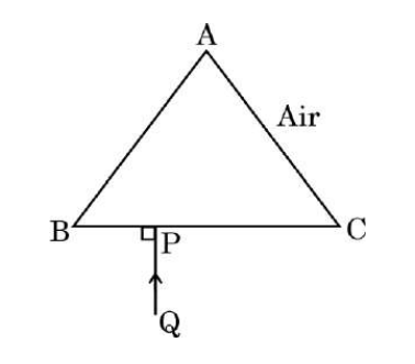
(iii) A ray of light QP is incident normally on the face BC of a triangular prism ABC of refractive index 1.5 kept in air, as shown in the figure. Trace the path of the ray as it passes through the prism and give relevant explanation.
(b) Derivation of refractive index of prism: Let A be the angle of the prism and δₘ be the angle of minimum deviation. When light passes through the prism at minimum deviation, the angle of incidence (i) is equal to the angle of emergence (e) and the refracted angles inside the prism are equal (r). Using geometry of prism, the angle A = r₁ + r₂ = 2r and the total deviation δₘ = (i + e) - A, but at minimum deviation i = e, so δₘ = 2i - A or i = (A + δₘ) / 2. Using Snell's law at the first face air to prism, sin i = μ sin r. Therefore, μ = sin i / sin r = sin((A + δₘ) / 2) / sin(A / 2). This is the required formula relating μ, A and δₘ.
(c) When a ray of light QP is incident normally on the face BC of the triangular prism ABC, it enters the prism without deviation since incidence is normal. Inside the prism, the ray bends at the other face AC because the light passes from denser medium (glass) to rarer medium (air). Due to refraction, the ray bends away from the normal at face AC and emerges out of the prism at some angle, causing the emergent ray RS to deviate from the original incident ray PQ. The overall deviation depends on the refractive index and angles of the prism. This explains the path of light through the prism when incident normally on one face.
(i) What is the difference between a ray and a wavefront ?
(ii) A plane wave is incident on a reflecting surface. Using Huygens principle, show how it is reflected from the surface. Hence, verify the law of reflection.
(iii) Depict refraction of a plane wave by a convex lens.
A wavefront is an imaginary line or surface joining all points of a wave that vibrate in phase. Rays are straight lines drawn perpendicular to the wavefronts showing the direction of wave propagation.
(ii) Reflection of a plane wave using Huygens principle and verification of law of reflection:
When a plane wave is incident on a reflecting surface, every point on the wavefront acts as a source of secondary wavelets according to Huygens principle. These wavelets spread out in the forward direction. The reflected wavefront is the envelope of these secondary wavelets. The angle of incidence (angle between incident ray and normal to the surface) i equals the angle of reflection r (angle between reflected ray and normal), which verifies the law of reflection: i = r.
(iii) Refraction of a plane wave by a convex lens:
When a plane wave is incident on a convex lens, the lens makes the wavefronts bend due to change in speed of light in the lens material. The convex lens converges the parallel incident wavefronts towards its principal focus, changing the direction of rays to converge. This bending of wavefronts is refraction, causing the rays to meet at the focal point of the lens.
(i) Define the terms (I) resonant frequency, and (II) power factor of a series LCR circuit. For what value of the power factor will the power dissipated in the circuit be maximum?
(ii) An inductor of 5/π H, a capacitor of 50/π μF and a resistor of 400 Ω are connected in series across an ac voltage v = 140 sin (100πt) V. Calculate:
(I) impedance of the circuit, and
(II) rms value of current that flows in the circuit.
(Take √2 = 1.4)
(II) Power factor of a series LCR circuit is the cosine of the phase angle between the voltage and current. It is given by cosϕ = R / Z, where R is resistance and Z is impedance of the circuit.
The power dissipated in the circuit is maximum when the power factor is 1, which occurs at the resonant frequency when Z = R and the phase angle ϕ = 0.
(ii) Given:
Inductance, L = 5 / π H, Capacitance, C = 50 / π μF = (50 / π) * 10-6 F, Resistance, R = 400 Ω, Voltage, v = 140 sin(100πt) V. Angular frequency, ω = 100π rad/s.
(I) Calculate inductive reactance, XL = ωL = 100π * (5 / π) = 500 Ω.
Calculate capacitive reactance, XC = 1 / (ωC) = 1 / (100π * 50 / π * 10-6) = 1 / (100 * 50 * 10-6) = 1 / 0.005 = 200 Ω.
Impedance, Z = sqrt(R2 + (XL - XC)2) = sqrt(4002 + (500 - 200)2) = sqrt(160000 + 90000) = sqrt(250000) = 500 Ω.
(II) Calculate rms voltage, Vrms = Vmax / sqrt(2) = 140 / 1.4 = 100 V.
Rms current, Irms = Vrms / Z = 100 / 500 = 0.2 A.
Final answers: (I) Impedance of the circuit, Z = 500 Ω.
(II) Rms current in the circuit, Irms = 0.2 A.
(i) Draw a labelled diagram of a step-up transformer. Obtain the ratio of secondary voltage to primary voltage in terms of number of turns in the two coils.
(ii) The number of turns in the primary and the secondary coil of an ideal transformer are 100 and 5000 respectively. If 3.3 kW power is supplied to the transformer at 220 V, find
(I) current in the primary coil, and (II) output voltage.
The ratio of secondary voltage (Vs) to primary voltage (Vp) is equal to the ratio of the number of turns in the secondary coil to that in the primary coil, i.e.,
Vs/Vp = Ns/Np
This means if Ns > Np, the output voltage is stepped up.
(ii)(I) Given: Power input P = 3.3 kW = 3300 W, Primary voltage Vp = 220 V, Number of turns Np = 100, Number of turns Ns = 5000.
Current in primary coil Ip = Power / Voltage = 3300 / 220 = 15 A.
(II) Using transformer relation, Vs/Vp = Ns/Np, so
Vs = Vp * (Ns/Np) = 220 * (5000 / 100) = 220 * 50 = 11000 V.
Therefore, the output voltage is 11000 V and the current in the primary coil is 15 A. This shows the transformer steps up the voltage from 220 V to 11000 V while the power remains the same in an ideal transformer.
(i) Explain the following statements giving reason:
(a) An equipotential surface through a point is normal to the electric field at that point.
(b) When a dielectric is placed in an external electric field, the electric field inside the dielectric is less than that outside it.
(c) The potential difference between the plates of a charged parallel plate capacitor decreases when its plates are brought closer.
(ii) Obtain an expression for the work done to dissociate the system of three charges q, –4q and 2q placed at the vertices A, B and C respectively of an equilateral triangle of side ‘a’.
(b) When a dielectric material is placed in an external electric field, its molecules get polarized, creating induced charges on the surfaces of the dielectric. This induced field inside the dielectric opposes the external field, reducing the net electric field inside the dielectric compared to the outside.
(c) The potential difference V between the plates of a capacitor is given by V = Q/C, where Q is charge and C is capacitance. Capacitance of a parallel plate capacitor is C = εΰ A/d, where d is the separation between plates. When the plates are brought closer (d decreases), capacitance C increases and since Q is constant, the potential difference V = Q/C decreases.
(ii) Charges at vertices A, B, C of equilateral triangle with side a are q, –4q and 2q respectively.
Work done to assemble the system = Electrostatic potential energy U of system
U = Sum of potential energies of all pairs = k * [q * (–4q)/a + q * 2q/a + (–4q) * 2q/a], where k = 1/(4πε₀)
= k * [(-4q2)/a + 2q2/a - 8q2/a] = k * (-10q2/a) = – 10k q2/a
Since work done to dissociate means separating charges to infinite distance, we need to do work equal to magnitude of potential energy. So, work done = 10k q2/a.
Where k = 1/(4πε₀).
(i) Answer the following giving reason:
(I) The electron drift speed is estimated to be only a few mm/s for currents in the range of a few amperes. How, then, is the current established almost the instant a circuit is closed?
(II) A low voltage supply from which one needs high currents must have very low internal resistance. Why?
(III) The assertion that V = IR is a statement of Ohm’s law is not true. Why?
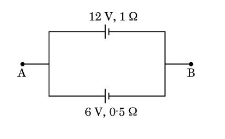
(ii) Two cells of emfs 12 V and 6 V are connected in parallel as shown in the figure. Their internal resistances are 1 Ω and 0.5 Ω respectively. Calculate the emf and internal resistance of the equivalent cell between points A and B.
(II) A low voltage supply supplying high current needs very low internal resistance because internal resistance reduces the terminal voltage and wastes power as heat inside the source. Low internal resistance ensures maximum voltage is available to the external circuit and minimizes power loss.
(III) Ohm's law states that V = IR is valid only for ohmic conductors where resistance remains constant. The assertion that it is a universal law is not true because many materials do not obey this linear relation; their resistance depends on factors like temperature, voltage, and current.
(ii) Given two cells connected in parallel:
Emf of cell 1, E1 = 12 V, internal resistance r1 = 1 Ω
Emf of cell 2, E2 = 6 V, internal resistance r2 = 0.5 Ω
The emf of the equivalent cell (E) is given by:
E = (E1/r1 + E2/r2) / (1/r1 + 1/r2)
= (12/1 + 6/0.5) / (1/1 + 1/0.5)
= (12 + 12) / (1 + 2) = 24 / 3 = 8 V
The internal resistance of equivalent cell (r) is:
r = 1 / (1/r1 + 1/r2) = 1 / (1 + 2) = 1/3 Ω = 0.333 Ω
Therefore, the equivalent cell between points A and B has an emf of 8 V and internal resistance 0.333 Ω.
Other Years — Physics