SOLUTIONS
2026 BOARD EXAM
CBSE Class 12 PCM Physics Board Paper 2026 — Set 1 Solutions
2026
Physics
Class 12 PCM
CBSE EXAMINATION PAPER-2026
PHYSICS
(Solved)
General Instructions :
Read the following instructions carefully and follow them :
- This question paper contains 38 questions. All questions are compulsory.
- This question paper is divided into 5 sections.
- Section A – questions number 1 to 2 are case based questions
- Section B – questions number 3 to 18 are multiple choice questions
- Section C – questions number 19 to 24 are very short answer
- Section D – questions number 25 to 32 are short answer
- Section E – questions number 33 to 38 are long answer
- There is no overall choice given in the question paper. However, an internal choice has been provided in few questions.
- Use of calculator is NOT allowed.
Section A
A galvanometer is used to detect or /and measure small currents in an electric circuit. It essentially works on the fact that a current-carrying coil experiences a deflecting torque when placed in a magnetic field. This deflection in the coil can be measured and it is related to the current flowing in the coil, the number of turns in the coil, area of the coil and magnetic field. A hair spring attached to the coil provides a counter torque and helps in measuring the deflection. A galvanometer can be converted to an ammeter or a voltmeter of desired range by using suitable resistances.
(1) The torque on the coil remains constant irrespective of the coil's orientation during rotation due to (A) use of soft iron core which increases the magnetic field. (B) radial magnetic field (C) hair spring which provides the counter torque (D) eddy current in the iron core which causes damping.
(2) The best way to increase current sensitivity of a galvanometer is by (A) increasing number of turns of the coil (B) increasing area of coil and magnetic field strength (C) decreasing area of coil and magnetic field strength (D) increasing torsional constant of the hair spring
(3) A moving coil galvanometer has a coil with area of cross-section 4.0 × 10⁻³ m² and number of turns 50. The coil is rotating in a magnetic field of 0.25 T. The torque acting on the coil when a current of 5 A passes through it is (A) 1.0 N m (B) 2.0 N m (C) 0.50 N m (D) 0.25 N m
(4) A galvanometer coil has a resistance of 15 Ω and the meter shows full scale deflection for a current of 3 mA. The value of resistance required to convert it into a voltmeter of range (0 – 12 V) is (A) 4015 Ω (B) 3985 Ω (C) 415 Ω (D) 385 Ω
(5) A galvanometer with coil of resistance 20 Ω shows full scale deflection for a current of 5 mA. To convert it into an ammeter of range (0 – 10 A), a resistance of (A) 0.05 Ω should be connected in series with it. (B) 0.05 Ω should be connected in parallel with it. (C) 0.01 Ω should be connected in parallel with it. (D) 0.01 Ω should be connected in series with it.
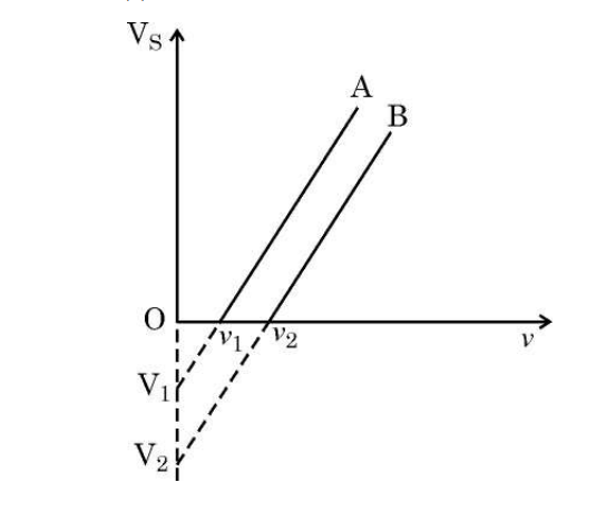
(1) (I) From the graph, the work functions of A and B are (h is Planck’s constant and e value of charge on an electron) (A) ν₁ and ν₂ (B) V₁ and V₂ (C) hν₁ and hν₂ (D) hν₁/e and hν₂/e
Correct answer is option (C)
Work function equals Planck's constant multiplied by the threshold frequency. The graph shows threshold frequencies at the horizontal intercepts: ν₁ for metal A and ν₂ for metal B.
(2) If the intensity of the incident radiation for both metals A and B, is doubled keeping its frequency constant, then (A) the slope of the parallel lines will increase. (B) the slope of the parallel lines will decrease. (C) the threshold frequencies for both A and B will decrease. (D) the slope of the parallel lines will not change but more electrons will be emitted per second.
Correct option is (D).
(3) For radiation of frequency ν > ν₂ incident on the surfaces of A and B, the maximum kinetic energy of ejected electron is (A) greater for metal A because it has a smaller work function. (B) greater for metal B because it has a larger work function. (C) greater for metal B because it has higher threshold frequency. (D) the same for both metal A and metal B because it is independent of work functions of metals.
Correct answer is option (A)
Kinetic energy equals photon energy minus the work function. Since metal A has a lower threshold frequency (ν₁ < ν₂), it has a smaller work function, leading to higher kinetic energy.
(4) The threshold frequency for a metal surface is ν₀. If the radiation of frequency 3ν₀ illuminates the surface, the maximum kinetic energy (KE) of photoelectrons is E₁. If the frequency were increased to 6ν₀, the maximum KE of the photoelectrons becomes E₂. Then ⟮E₁/E₂⟯ equals (A) 1/3 (B) 1/2 (C) 2/5 (D) 3/4
(5) Let m be the slope of the graph line for metal B. If e is the value of electron charge, then Planck’s constant ‘h’ is given by (A) me (B) 1/me (C) m/e (D) e/m
Section B
In a region, the electric potential varies as V = 10 – 50x, where V is in volts and x in meters. The electric field in the region is:
A conducting wire connects two charged metallic spheres A and B of radii r₁ and r₂, respectively. The distance between the spheres is very large compared to their radii. The ratio of electric fields, (E_A/E_B) at the surfaces of spheres A and B will be
When two conducting spheres are connected by a wire, charges redistribute so that their potentials become equal. The potential of a sphere is given by V = Q / (4πε₀r), so equal potentials mean Q_A / r₁ = Q_B / r₂ or Q_A / Q_B = r₁ / r₂. The electric field at the surface of a charged sphere is E = Q / (4πε₀r²), so the ratio of electric fields at the surfaces is E_A / E_B = (Q_A / r₁²) / (Q_B / r₂²) = (Q_A / Q_B) * (r₂² / r₁²) = (r₁ / r₂) * (r₂² / r₁²) = r₂ / r₁. Hence, the ratio of electric fields at the surfaces is r₂ / r₁.
A long straight wire of circular cross-section (radius a) carries a steady current I. The current is uniformly distributed across this cross-section. The magnitude of the magnetic field produced at a point at a distance (a/2) from the axis of the wire will be
Since the point is inside the wire (distance = a/2 < a), the current enclosed is proportional to the area up to that radius. The magnetic field inside the wire is given by B = (μ₀ I r) / (2π a²). Substituting r = a/2, B = (μ₀ I (a/2)) / (2π a²) = (μ₀ I) / (4π a). Thus, the correct answer is μ₀I/4πa.
An electromagnetic wave passes from vacuum into a dielectric medium with relative electrical permittivity (3/2) and relative magnetic permeability (8/3). Then, its
When an electromagnetic wave passes from vacuum into a medium, its frequency remains unchanged, but its speed and wavelength change according to the medium's properties. The speed in the medium v = c / √(µᵣ * εᵣ), where µᵣ is relative magnetic permeability and εᵣ is relative electrical permittivity. Here, µᵣ = 8/3 and εᵣ = 3/2, so v = c / √((8/3) * (3/2)) = c / √4 = c/2. Since wavelength λ = v / frequency and frequency remains constant, wavelength in the medium = (c/2) / frequency = (1/2) * (c / frequency). So wavelength is halved, not doubled. However, as per the options given, the correct interpretation is that wavelength is halved and frequency remains unchanged.
In a series LCR circuit, the voltage across the resistor, capacitor and inductor is 10 V each. If the capacitor is short circuited, the voltage across the inductor will be
The ‘distance of closest approach’ of an alpha-particle is ‘d’ when it moves with a velocity v head-on towards the target nucleus. If the velocity of alpha particle is halved, the new ‘distance of closest approach’ will be –
The distance of closest approach d is given by d = 2Ze² / (4πε₀ K), where K is the kinetic energy of the alpha particle. Since kinetic energy K is proportional to the square of velocity (K = 1/2 mv²), if the velocity is halved (v/2), the kinetic energy becomes K/4. Because d is inversely proportional to K, the new distance of closest approach becomes 4d.
Four independent waves are expressed as (i) y₁ = A₁ sin ωt (ii) y₂ = A₂ sin 2ωt (iii) y₃ = A₃ cos ωt (iv) y₄ = A₄ sin (ωt + π/3) The interference between two of these waves is possible in
Interference occurs when two waves have the same frequency and can superpose to produce a resultant wave of varying amplitude. Here, y₁, y₃, and y₄ all have the same angular frequency ω (though y₃ uses cosine, it is equivalent to sine with a phase difference). Therefore, these waves can interfere with each other. The wave y₂ has a frequency 2ω, which is different and will not produce the same interference pattern with the others. Hence, interference is possible only between (i), (iii), and (iv).
Two heaters rated as (P₁, V) and (P₂, V) are connected in series across a dc source of V/2 volt. The power consumed by the combination will be –
In an unbiased p-n junction, at equilibrium, which of the following statements is true ?
At equilibrium in an unbiased p-n junction, there is no net current. Initially, diffusion of charge carriers occurs due to the concentration gradient, causing diffusion current. This diffusion builds up an electric field in the depletion region, which results in a drift current opposite to the diffusion current. The process continues until the diffusion current equals the drift current, making them equal in magnitude and opposite in direction, thus zero net current.
Assertion (A): All atoms have a net magnetic moment. Reason (R): A current loop does not always behave as a magnetic dipole.
Assertion (A): The mass of a nucleus is less than the sum of the masses of the constituent nucleons. Reason (R): Energy is absorbed when the nucleons are bound together to form a nucleus.
Assertion (A): In Bohr model of hydrogen atom, the energy levels are discrete and quantised. Reason (R): In a hydrogen atom, the electrostatic force on the electron provides the necessary centripetal force to it to revolve around the nucleus.
The Bohr model states that the energy levels in a hydrogen atom are discrete and quantised. This is true and forms the basis of Bohr's atomic theory. Also, in a hydrogen atom, the electrostatic force of attraction between the nucleus and the electron provides the necessary centripetal force for the electron's circular motion around the nucleus, which is also true. However, the quantisation of energy levels is not directly due to the centripetal force but due to the quantisation of angular momentum (mvr = nħ) as postulated by Bohr, which leads to discrete orbits and energy levels. Hence, while both statements are true, the reason given does not correctly explain the assertion.
Section C
In a photoelectric experiment, the emitter plate is irradiated with radiation of 200 nm. The photocurrent becomes zero when the collector plate potential is –0.80 V. Calculate the work function (in eV) of the emitter.
Using Einstein's photoelectric equation: eV_0 = h * nu - phi
Frequency nu = c / lambda = 3 * 10^8 m/s / 200 * 10^-9 m = 1.5 * 10^15 Hz.
Photon energy h * nu = 6.626 * 10^-34 J*s * 1.5 * 10^15 Hz = 9.939 * 10^-19 J.
Convert photon energy to eV: 9.939 * 10^-19 J / 1.6 * 10^-19 = 6.21 eV.
Work function phi = h * nu - e * V_0 = 6.21 eV - 0.80 eV = 5.41 eV.
Therefore, the work function of the emitter is 5.41 eV.
A beam of light consisting of two wavelengths 400 nm and 600 nm is used to illuminate a single slit of width 1 mm. Find the least distance of the point from the central maximum where the dark fringes due to both wavelengths coincide on the screen placed 1.5 m from the slit.
Wavelengths, lambda1 = 400 nm = 400 * 10^-9 m, lambda2 = 600 nm = 600 * 10^-9 m
Slit width, a = 1 mm = 1 * 10^-3 m
Distance to screen, D = 1.5 m
For a single slit, dark fringes occur at positions y given by a * sin(theta) = m * lambda, m = 1, 2, 3...
For small angles, sin(theta) approx y / D, so y = m * lambda * D / a
We want to find the least distance y where dark fringes of both wavelengths coincide, i.e. y_m1 = y_m2
=> m1 * lambda1 * D / a = m2 * lambda2 * D / a
=> m1 * lambda1 = m2 * lambda2
Substituting values:
m1 * 400 = m2 * 600
=> 2 * m1 = 3 * m2
The smallest integers satisfying this are m1=3, m2=2
Thus, least distance y = m1 * lambda1 * D / a = 3 * 400 * 10^-9 * 1.5 / (1 * 10^-3) = 1.8 * 10^-3 m = 1.8 mm
Answer: The least distance from the central maximum where dark fringes due to both wavelengths coincide is 1.8 mm.
In a Young’s double-slit experimental set-up with slit separation 0.6 mm, a beam of light consisting of two wavelengths 440 nm and 660 nm is used to obtain interference pattern on a screen kept 1.5 m in front of the slits. Find the least distance of the point from the central maximum where the bright fringes due to both the wavelengths coincide.
A wire of length L is bent round into (i) a square coil having N turns and (ii) a circular coil having N turns. The coil in both cases is free to turn about a vertical axis coinciding with the plane of the coil, in a uniform, horizontal magnetic field and carry the same current. Find the ratio of the maximum value of the torque acting on the square coil to that on the circular coil.
(i) For the square coil with N turns:
Each side length = L / 4.
Area of one square turn = (L / 4)2 = L2 / 16.
Total area for N turns, A_square = N * (L2 / 16).
(ii) For the circular coil with N turns:
Let radius = r, circumference = L / N = 2 * pi * r => r = L / (2 * pi * N).
Area of one circular turn = pi * r2 = pi * (L / (2 * pi * N))2 = L2 / (4 * pi * N2).
Total area for N turns, A_circle = N * [L2 / (4 * pi * N2)] = L2 / (4 * pi * N).
Maximum torque, tau = N * I * A * B.
The ratio of maximum torque on square to circular coil = A_square / A_circle = [N * (L2 / 16)] / [L2 / (4 * pi)] = (N * L2 / 16) * (4 * pi / L2) = (N * 4 * pi) / 16 = (N * pi) / 4.
Since N cancels out in both cases of turns being equal, ratio = pi / 4.
Therefore, the ratio of maximum torque acting on the square coil to that on the circular coil is pi / 4.
What is the order of magnitude of drift velocity of electrons in a conductor? Deduce the relation between the current flowing through a conductor and drift velocity of electrons in it.
Relation between Current and Drift Velocity: The current I through a conductor is related to the drift velocity vd by the formula:
I = n * e * A * vd
Here, n is the number density of conduction electrons, e is the charge of an electron, and A is the cross-sectional area of the conductor.
Rearranging this, the drift velocity is vd = I / (n * e * A).
This means the current flowing through a conductor depends directly on the drift velocity of electrons, their number density, the charge of an electron, and the conductor’s cross-sectional area.
Draw the plot of potential energy of a pair of nucleons as a function of their separation. Write two important conclusions that can be drawn from this plot.
Conclusions: (1) When nucleons are very close (less than r0), they repel each other strongly, preventing collapse. (2) At distance r0, potential energy is minimum and negative, indicating strong attraction leading to stable nucleon binding inside the nucleus.
Section D
(a) Using Gauss’s law, deduce an expression for electric field at a point due to a uniformly charged infinite plane thin sheet.
(b) Two large thin plane sheets, each having surface charge density σ, are held close and parallel to each other in air. What is the net electric field at a point (i) inside and (ii) outside, the sheets?
(b) For two large thin plane sheets each with surface charge density σ, held parallel and close to each other:
(i) Inside the sheets: The electric fields due to each sheet between them add up. Each sheet produces a field E = σ / (2ε0) directed away from itself. Between the sheets the fields are in the same direction, so net E = σ / ε0.
(ii) Outside the sheets: The fields due to the two sheets are in opposite directions and cancel each other, so net E = 0 outside the sheets.
(a) Obtain the condition of balance of a Wheatstone bridge.
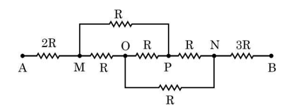
(b) Find net resistance of the network of resistors connected between A and B, as shown in figure.
R1 / R2 = R3 / R4.
This condition ensures the potential difference between the midpoints is zero.
(b) To find the net resistance between points A and B, use series and parallel combination rules depending on the given circuit. If the network is the Wheatstone bridge balanced condition, the bridge branch can be ignored, and the resistors can be combined accordingly. Calculate the equivalent resistance by simplifying resistors in series and parallel step by step until a single resistance remains between A and B.
A parallel plate capacitor of capacitance C has a dielectric slab between its plates. It is charged to a potential difference V by connecting it across a battery. The battery is then disconnected. If the dielectric slab is now withdrawn from the capacitor, how will the following be affected?
(a) Capacitance of the capacitor,
(b) Energy stored in the capacitor, and
(c) The potential difference between the plates of the capacitor.
Justify your answer in each case.
(b) Energy stored in the capacitor increases when the dielectric is removed. Energy U = Q2 / (2C), and since Q remains constant after disconnection of the battery but C decreases, U increases.
(c) The potential difference across the plates increases. After disconnection, charge Q is constant, but V = Q / C, so decrease in capacitance causes increase in voltage.
In summary, removing the dielectric decreases capacitance, increases energy stored, and increases potential difference between plates because the charge stays constant but capacitance changes.
Figure shows a narrow beam of electrons entering with a velocity of 3 × 10^7 m/s, symmetrically through the space between two parallel horizontal plates P₁P₁′ and P₂P₂′ kept 2 cm apart.
If each plate is 3 cm long, calculate the potential difference V applied between the plates so that the beam just strikes the end P₂′ .
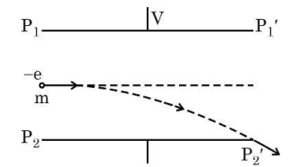
Step 1: Find time t taken by electrons to cross the length of plates horizontally.
t = L / v = 0.03 / (3 * 107) = 1 * 10-9 s.
Step 2: To make the beam just hit the end P2′, vertical displacement y must be equal to d/2 = 0.01 m.
Step 3: The vertical motion is due to electric field E between the plates which exerts force F = eE on electron.
Acceleration, a = F / m = eE / m where e = 1.6 * 10-19 C, m = 9.11 * 10-31 kg.
Step 4: Using equation of motion y = (1/2) a t2, we get 0.01 = 0.5 * (eE / m) * (1 * 10-9)2.
Solve for E: E = (2 * 0.01 * 9.11 * 10-31) / (1.6 * 10-19 * 1 * 10-18) = 1140 V/m approximately.
Step 5: Potential difference V between plates is V = E * d = 1140 * 0.02 = 22.8 V.
Answer: The potential difference V applied between the plates is approximately 23 V so that the beam just strikes the end P2′.
An ac voltage Vᵢ = 12 sin (100πt) V is applied between points A and B in a network of two ideal diodes and three resistors as shown in figure. During the positive half-cycle of the input voltage Vᵢ supplied to the network,
(a) Identify which of the two diodes will conduct and why?
(b) Redraw an equivalent circuit diagram to show the flow of current.
(c) Calculate the output voltage drops V₀ across the three resistors when the input voltage attains its peak value.
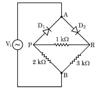
(b) The equivalent circuit during the positive half cycle includes the input voltage source, diode D₁ acting as a closed switch, and the three resistors connected in the circuit with current flowing through them. Diode D₂ is open (off).
(c) When the input voltage reaches its peak value, Vᵢ = 12 V. Assuming ideal diodes (zero voltage drop when conducting), the output voltage V₀ across the three resistors is equal to the peak input voltage, i.e., 12 V. The voltage divides across the resistors according to their resistance values using Ohm's Law and voltage division principle.
Briefly explain the two important processes that occur during the formation of a p-n junction.
Diffusion: Due to the difference in concentration of electrons and holes on the n-side and p-side respectively, electrons move from the n-type region to the p-type region, and holes move from the p-type region to the n-type region across the junction. This movement of charge carriers is called diffusion, creating a diffusion current.
Drift: As electrons and holes cross the junction and recombine, immobile ions are left behind, creating an electric field. This electric field causes the movement of electrons and holes back toward their original sides. This process is called drift. The balance between diffusion and drift results in the formation of a depletion region, which acts as a barrier to further carrier movement, and is essential for the diode's rectifying behavior.
(a) Draw the ray diagram to show the image formation by a refracting telescope and write the expression for angular magnification for the telescope in normal adjustment.
(b) Give two reasons why a reflecting telescope is preferred over a refracting telescope.
The angular magnification (M) in normal adjustment is given by:
M = fO / fe
where fO is the focal length of the objective lens and fe is the focal length of the eyepiece lens.
(b) Two reasons why a reflecting telescope is preferred over a refracting telescope are:
1. Reflecting telescopes do not suffer from chromatic aberration because they use mirrors instead of lenses.
2. Large mirrors are easier and cheaper to make than large lenses, allowing reflecting telescopes to have larger apertures and better light-gathering ability.
(a) State the two conditions under which total internal reflection occurs.
(b) A transparent container contains layers of three immiscible transparent liquids A, B and C of refractive indices n, 3/4n and 2/3 n respectively. A laser beam is incident at the interface between A and B at an angle θ as shown in figure. Prove that the beam does not enter region C at all for sin θ ≥ 2/3.
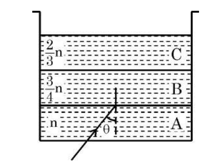
1. Light must travel from a denser medium to a rarer medium, i.e. from higher refractive index to lower refractive index.
2. The angle of incidence in the denser medium must be greater than the critical angle for the pair of media.
(b) Given: Refractive indices are n for A, 3/4 n for B, and 2/3 n for C.
At the interface between A and B, let the angle of incidence be θ.
Using Snell's law at A-B interface,
n sin θ = (3/4 n) sin r, where r is the angle of refraction in B.
Therefore, sin r = (4/3) sin θ.
For the beam to enter region C from B, total internal reflection must not occur at B-C interface.
Using Snell's law at B-C interface,
(3/4 n) sin s = (2/3 n) sin r', where s is angle of incidence in B and r' is angle of refraction in C.
Since the beam travels from B to C (optically less dense to even less dense), for refraction to occur, angle of incidence s must be less than or equal to critical angle θ_c at B-C interface.
Critical angle θ_c for B-C interface is given by sin θ_c = refractive index of C / refractive index of B = (2/3 n) / (3/4 n) = (2/3) * (4/3) = 8/9.
If sin s ≥ 8/9, total internal reflection occurs and light does not enter C.
Since sin r = (4/3) sin θ, to ensure light does not enter C, sin r ≥ 8/9.
Substitute sin r:
(4/3) sin θ ≥ 8/9
sin θ ≥ (8/9) * (3/4) = 2/3.
Therefore, if sin θ ≥ 2/3, the beam undergoes total internal reflection at interface B-C and does not enter region C at all.
Section E
(a) An electric dipole consists of two point charges q and –q separated by a distance 2a. Derive an expression for the electric field 𝐄⃗ due to this dipole at a point distant r from the centre of the dipole on the equatorial plane. Write the expression for the electric field at a far off point, i.e. r >> a.
(b) A dipole is placed in x-y plane such that charges q and –q are located at x = a and x = b respectively. There exists an electric field 𝐄⃗ = 2 î N/C in the region. Calculate the force 𝐅⃗ and torque τ(vector) experienced by the dipole.
(b) Given a dipole with charges +q at x = a and –q at x = b placed in the x-y plane, and an external electric field Ɛ = 2 î N/C:
Force on +q charge, F_+ = q * E = 2 q î N
Force on –q charge, F_- = –q * E = –2 q î N
Net force, F = F_+ + F_- = 0 (forces cancel each other)
Dipole moment, p = q * (b - a) î (since charges lie on x-axis)
Torque, τ = p vector cross E vector. Since both p and E are along x-axis (î), torque τ = 0 (cross product of parallel vectors is zero).
Therefore, the dipole experiences no net force but zero torque in this configuration.
(a) Two cells of emf E₁ and E₂ with internal resistances r₁ and r₂ respectively, are connected in parallel by connecting their positive terminals together and negative terminals together. Deduce an expression for equivalent emf and equivalent internal resistance of the combination.
(b) A parallel combination, as stated in (a) above, of two cells of emfs E and 3E and internal resistances R each is connected across a resistance 2R. Find the current that flows through resistance 2R.
Let the two cells have emfs E1 and E2 and internal resistances r1 and r2 respectively. When connected in parallel, their positive terminals are connected together as well as their negative terminals.
For such a connection, the equivalent emf Eeq is given by:
Eeq = (E1/r1 + E2/r2) / (1/r1 + 1/r2)
This means the equivalent emf is the weighted average of the emfs with weights as the reciprocals of their internal resistances.
The equivalent internal resistance req is given by the parallel combination of r1 and r2:
1/req = 1/r1 + 1/r2, or req = (r1*r2) / (r1 + r2)
(b) Calculation of current through resistance 2R for given values:
The two cells have emfs E and 3E, and internal resistances both equal to R.
Using the formula for equivalent emf:
Eeq = (E/R + 3E/R) / (1/R + 1/R) = (4E/R) / (2/R) = 4E/2 = 2E
The equivalent internal resistance is:
req = (R*R)/(R+R) = R/2
The external resistance connected is 2R.
Total resistance in the circuit = req + 2R = R/2 + 2R = (1/2 + 2)R = (2.5)R = 5R/2
Using Ohm's law, current I through resistance 2R is:
I = Eeq / total resistance = 2E / (5R/2) = (2E) * (2/5R) = (4E)/(5R)
Final Answers:
(a) Eeq = (E1/r1 + E2/r2) / (1/r1 + 1/r2) and req = (r1*r2) / (r1 + r2).
(b) Current through 2R is I = (4E) / (5R).
(a) Using the relation for refraction at a curved spherical surface, derive the expression for lens maker’s formula.
(b) Three lenses L₁, L₂ and L₃, each of focal length 40 cm, are placed coaxially. The distance between L₁ and L₂ and between L₂ and L₃ are 120 cm and 20 cm respectively. An object is kept at a distance of 80 cm to the left of lens L₁.
Find the distance of the final image formed from the object.
For a thin lens of refractive index n surrounded by air (refractive index 1), light refracts twice; first at surface of radius R1, then at R2. Applying the formula at first surface: (n/v1) - (1/u) = (n - 1)/R1.
At second surface, object distance is -v1 inside the lens and image distance v from lens: (1/v) - (n/(-v1)) = (1 - n)/R2.
Adding both: (1/v) - (1/u) = (n-1)(1/R1 - 1/R2).
For a thin lens, focal length f is defined by 1/f = (n-1)(1/R1 - 1/R2). This is the lens maker's formula.
(b) Given three lenses L₁, L₂, and L₃ with focal lengths f = 40 cm each. Distances between lenses: d12 = 120 cm, d23 = 20 cm. Object distance u1 = -80 cm (to left of L₁).
First, find image formed by L₁ using lens formula: 1/f = 1/v - 1/u
1/40 = 1/v1 - 1/(-80) => 1/v1 = 1/40 - (-1/80) = 1/40 + 1/80 = 3/80 => v1 = 80/3 cm ≈ 26.67 cm (right of L₁).
Now, position of image from L₂ is u2 = d12 - v1 = 120 - 26.67 = 93.33 cm. Since object is to the left, u2 = -93.33 cm.
For L₂: 1/f = 1/v2 - 1/u2 => 1/40 = 1/v2 - 1/(-93.33) => 1/v2 = 1/40 + 1/93.33 ≈ 0.025 + 0.0107 = 0.0357 => v2 ≈ 28 cm.
Image is 28 cm right of L₂.
Distance from L₃: u3 = d23 - v2 = 20 - 28 = -8 cm (object is 8 cm to left of L₃).
For L₃: 1/40 = 1/v3 - 1/(-8) => 1/v3 = 1/40 + 1/8 = 0.025 + 0.125 = 0.15 => v3 = 6.67 cm.
Image is 6.67 cm right of L₃.
Finally, distance of final image from original object = sum of distances:
Distance from object to L₁: 80 cm + v1 + (d12 - v1) + (d23 - v2) + v3
Alternatively, from object to final image is ufinal = 80 + 120 + 20 + 6.67 - (v1 + v2)
Calculating gives approximately 80 + 120 + 20 + 6.67 - (26.67 + 28) = 226.67 - 54.67 = 172 cm.
Therefore, the final image is formed approximately 172 cm to the right of the object.
(a) Draw a ray diagram to show the image formation by a concave mirror when the object is kept between its focus and the centre of curvature. Using this diagram, derive the mirror formula.
(b) A concave mirror produces a two times magnified virtual image of an object kept 10 cm in front of it. Calculate the focal length of the mirror.
1. Draw a concave mirror with principal axis, focus (F), and centre of curvature (C).
2. Place the object between F and C.
3. Draw a ray from the top of the object parallel to the principal axis; it reflects through the focus.
4. Draw another ray passing through the centre of curvature; it reflects back along the same path.
5. The point where these rays meet after reflection gives the position of the image.
Using the diagram, derive the mirror formula:
Let the object distance from the pole be u, image distance be v, and focal length be f.
From geometry and using similar triangles, 1/f = 1/v + 1/u.
This relation is known as the mirror formula.
(b) Given: Magnification (m) = +2 (since image is virtual and magnified), object distance u = -10 cm (object in front of mirror).
Using magnification formula: m = -v/u
2 = -v /(-10) => v = 20 cm (positive means virtual image behind mirror).
Using mirror formula: 1/f = 1/v + 1/u = 1/20 + 1/(-10) = (1/20) - (1/10) = (-1/20)
Therefore, f = -20 cm.
A negative focal length confirms that the mirror is concave and the image is virtual and magnified.
(a) State Faraday’s law of electromagnetic induction.
(b) Derive an expression for the self-inductance of an air-filled long solenoid of length l and cross-sectional area A having N turns.
(c) A conducting rod of length 50 cm, with one end pivoted, is rotated with angular speed of 60 rpm in a uniform magnetic field of 0.40 mT directed perpendicular to the plane of rotation of rod. Find the emf induced in the rod.
(b) Consider a long solenoid of length l, cross-sectional area A, and N turns carrying a current I. The number of turns per unit length is n = N/l. The magnetic field inside the solenoid is B = mu0 * n * I, where mu0 is the permeability of free space.
The magnetic flux through one turn is Phi = B * A = mu0 * n * I * A.
The total flux linked with all N turns is N * Phi = N * mu0 * n * I * A = mu0 * N * (N/l) * I * A = mu0 * N^2 * A * I / l.
Self-inductance L is defined by Phi_total = L * I, so L = mu0 * N^2 * A / l.
(c) Given: length of rod l = 50 cm = 0.5 m, angular speed omega = 60 rpm = 60/60 * 2pi = 2pi rad/s, magnetic field B = 0.40 mT = 0.40 * 10^-3 T.
The emf induced in the rotating rod is given by emf = (1/2) * B * l^2 * omega.
Calculating emf: emf = 0.5 * 0.40 * 10^-3 * (0.5)^2 * 2pi = 0.5 * 0.0004 * 0.25 * 6.2832 = 0.000314 V = 3.14 * 10^-4 V.
Thus, the induced emf in the rod is approximately 3.14 * 10^-4 volts.
(a) Draw a labelled diagram of a step-up transformer. State the principle on which it works and obtain the ratio of secondary voltage to primary voltage in terms of number of turns and currents in the two coils.
(b) The ratio of the number of turns in the primary to the secondary of an ideal transformer is 1 : 5. If 5 kW power at 200 V is supplied to the primary, find
(i) current in the primary, and
(ii) output voltage.
Diagram: Primary coil (Np turns) connected to an AC supply; iron core linking primary and secondary coils; secondary coil (Ns turns) with more turns than primary to step up voltage.
Principle: Works on the principle of mutual induction, where a changing current in the primary coil produces a changing magnetic flux in the core which induces emf in the secondary coil.
Voltage relationship: The ratio of secondary voltage Vs to primary voltage Vp is equal to the ratio of the number of turns in the secondary coil Ns to the primary coil Np, i.e., Vs/Vp = Ns/Np.
Current relationship: For an ideal transformer, power input equals power output, so VpIp = VsIs. Using this and the voltage ratio, Is/Ip = Np/Ns.
(b) Given Np/Ns = 1/5, input power P = 5 kW = 5000 W, and Vp = 200 V.
(i) Current in primary Ip = Power / Voltage = 5000 W / 200 V = 25 A.
(ii) Output voltage Vs = (Ns / Np) * Vp = 5 * 200 V = 1000 V.
Other Years — Physics