SOLUTIONS

2026 BOARD EXAM

CBSE Class 12 PCM Physics Board Paper 2026 — Set 2 Solutions

2026

Physics

Class 12 PCM

CBSE EXAMINATION PAPER-2026

PHYSICS

(Solved)

Time allowed : 3 hours

Maximum Marks : 82

General Instructions :

Read the following instructions carefully and follow them :

  1. This question paper contains 38 questions. All questions are compulsory.
  2. This question paper is divided into 5 sections.
  3. Section A – questions number 1 to 2 are case based questions
  4. Section B – questions number 3 to 18 are multiple choice questions
  5. Section C – questions number 19 to 24 are very short answer
  6. Section D – questions number 25 to 32 are short answer
  7. Section E – questions number 33 to 38 are long answer
  8. There is no overall choice given in the question paper. However, an internal choice has been provided in few questions.
  9. Use of calculator is NOT allowed.

Section A

Question 1. A p-type or n-type semiconductor can be converted into a p-n junction by doping it with suitable impurity. The motion of majority charge carriers causes diffusion current across the junction while the barrier electric field causes motion of minority carriers for drift current. In case of unbiased diode, the diffusion and drift currents are equal. This equilibrium is disturbed by the biasing batteries. Diodes, therefore, allow currents in one direction. This property of diode is used in making rectifiers.

(1)

Silicon is doped with which of the following to obtain p-type semiconductor?

(A) Phosphorus

(B) Arsenic

(C) Boron

(D) Antimony

[1 Mark]
Answer: Silicon is doped with Boron to obtain a p-type semiconductor because Boron is a trivalent atom that creates holes by accepting electrons. As mentioned in the case, p-type semiconductors have more holes than electrons due to doping with trivalent atoms like Boron. Therefore, the correct answer is option (C) Boron.
Key Points: Silicon doped with trivalent atoms forms p-type semiconductor - Boron is a trivalent atom causing holes - p-type semiconductor has holes as majority carriers

(2)

A semiconductor has an electron concentration of 5 × 10²² m⁻³. The concentration of holes is (given nᵢ = 1.5 × 10¹⁶ m⁻³)

(A) 5 × 10²² m⁻³

(B) 1.5 × 10⁶ m⁻³

(C) 9 × 10⁸ m⁻³

(D) 4.5 × 10⁹ m⁻³

[1 Mark]
Answer: Given electron concentration n = 5 * 1022 m-3 and intrinsic carrier concentration ni = 1.5 * 1016 m-3. For a semiconductor, n * p = ni2, so p = ni2 / n = (1.5 * 1016)2 / (5 * 1022) = 4.5 * 109 m-3. Hence the concentration of holes is 4.5 * 109 m-3. This matches option (D). This also shows the number of holes is much smaller in an n-type semiconductor as explained in the case passage.
Key Points: Electron concentration n = 5 * 1022 m-3 - Intrinsic carrier concentration ni = 1.5 * 1016 m-3 - Use relation n * p = ni2 to find holes concentration p

(3)

During forward biasing of a p-n junction diode, the

(A) current is mainly due to drifting of majority carriers

(B) current is mainly due to drifting of minority carriers

(C) diffusion and drift currents are equal

(D) current is of the order of 1 A

[1 Mark]
Answer: During forward bias of a p-n junction diode, the current is mainly due to the diffusion of majority charge carriers across the junction, as the barrier is reduced allowing them to cross easily. Minority carriers also contribute by drifting, but the dominant current is due to diffusion, which makes the diode conduct current in one direction as explained in the case passage.
Key Points: Forward bias reduces barrier potential - Majority carriers cause diffusion current - Diode conducts current mainly by diffusion in forward bias

(4)

The threshold voltage for silicon diode is about

(A) 0.2 V

(B) 0.5 V

(C) 0.7 V

(D) 1.5 V

[1 Mark]
Answer: The threshold voltage of a silicon diode is about 0.7 V.
This is the minimum forward voltage at which the diode starts to conduct.
This value is based on the energy barrier created at the p-n junction, as explained in the case paragraph about barrier electric field and diffusion current.
Key Points: Threshold voltage - Silicon diode - Approximately 0.7 V

(5)

When we dope Ge with a pentavalent element, four of its electrons bond with four germanium neighbours but fifth electron remains weakly bound. The ionisation energy for this electron is about

(A) 0.01 eV

(B) 0.05 eV

(C) 0.1 eV

(D) 0.15 eV

[1 Mark]
Answer: When Ge is doped with a pentavalent element, the fifth electron is weakly bound and has an ionisation energy of about 0.01 eV. This low energy is much less than the 0.72 eV required to jump the forbidden band in intrinsic Ge, so the pentavalent impurity easily donates this electron for conduction, making it a donor impurity as explained in the case passage.
Key Points: Ge doped with pentavalent element has a fifth weakly bound electron - Ionisation energy of this electron is about 0.01 eV - Pentavalent impurity acts as donor providing free electrons for conduction
Question 2. In an experiment with convex lens of focal length f, the screen is fixed at a distance D from the object. A student slowly moves the lens away from the object towards the screen and finds that he is able to form sharp image of the object for two positions of the lens. The distance between these two positions of the lens is d.

(1)

The value of d is

(A) √D(D − 4f)

(B) √D(D − 2f)

(C) 2√(Df)

(D) √D(D − f)

[1 Mark]
Answer:

Correct answer is option (A)

According to the lens displacement method, the focal length is given by the formula: f = (D^2 - d^2) / 4D. Rearranging this equation to solve for d gives d = √[D(D - 4f)].

Key Points:

(2)

Compared to the size of the object, the images formed in the two positions are respectively

(A) reduced, enlarged

(B) reduced, reduced

(C) enlarged, enlarged

(D) enlarged, reduced

[1 Mark]
Answer:

Correct answer is option (d)

When the lens is closer to the object, the image distance is greater than the object distance, creating an enlarged image. As the lens moves closer to the screen, the object distance becomes greater than the image distance, creating a reduced image.


Key Points:

(3)

If the distance between object and screen is 80.00 cm and the lens forms sharp images at two positions separated by 20.00 cm, the focal length of convex lens is

(A) 15.50 cm

(B) 18.75 cm

(C) 20.50 cm

(D) 22.75 cm

[1 Mark]
Answer: Given the distance between object and screen D = 80.00 cm and the distance between two positions of lens d = 20.00 cm. The focal length f of the lens is given by the formula f = (D2 - d2)/4D = (802 - 202)/ (4 * 80) = (6400 - 400)/320 = 6000/320 = 18.75 cm. Hence, the focal length of the convex lens is 18.75 cm which is option (B).
Key Points: Two positions of lens give sharp images - Distance between object and screen is D - Focal length f = (D^2 - d^2)/4D formula used

(4)

Consider a convex lens of focal length 15 cm. For which of the following values of object-screen distance, two positions of the lens can be found to obtain sharp image on the screen?

(A) 45 cm

(B) 50 cm

(C) 55 cm

(D) 65 cm

[1 Mark]
Answer:

Correct answer is Option (D)

For two real distinct images to form on the screen in the displacement method, the distance between the object and the screen must be strictly greater than four times the focal length (D > 4f).

4f = 4 * 15 cm = 60 cm

only 65 cm is greater than 60 cm.

Key Points:

(5)

A thin convex lens of focal length 10 cm and another thin lens of focal length ‘f’ are placed coaxially in contact. If the power of their combination is 10/ 3 D, the value of ‘f’ is

(A)–15 cm

(B) –10 cm

(C) –20 cm

(D) –30 cm

[1 Mark]
Answer: The power P of the combination is given by P = P1 + P2 where P1 = 100/10 = 10 D (for 10 cm lens). Given total power = 10/3 D, so 10 + P2 = 10/3, hence P2 = 10/3 - 10 = -20/3 D. Focal length f = 100/P2 = 100/(-20/3) = -15 cm. Therefore, the value of f is – 15 cm, option (A). This uses the concept of combining powers mentioned in the case.
Key Points: Power of combined lens = sum of individual powers - Power of lens with focal length 10 cm is 10 D - Calculated power of second lens is -20/3 D corresponding to focal length -15 cm

Section B

Question 3.

Three point charges 2q, –2q and q are kept at the vertices of an equilateral triangle of side l. The potential energy of the system is

[1 Mark]
  • (A) –q²/(πϵ₀l)
  • (B) q²/(2πϵ₀l)
  • (C) zero
  • (D) –2q²/(πϵ₀l)
Explanation: The potential energy of a system of point charges is given by the sum of the potential energies of each pair of charges: U = (1/4πε₀)(q_1 q_2 /r_12 + q_2 q_3 /r_23 + q_3 q_1 /r_31). Here, the charges are 2q, –2q and q placed at the vertices of an equilateral triangle of side l, so all separations are equal to l. Therefore, potential energy U = (1/4πε₀)[(2q)(-2q)/l + (-2q)(q)/l + (q)(2q)/l] = (1/4πε₀)(-4q² - 2q² + 2q²)/l = (1/4πε₀)(-4q²)/l = –q²/(πε₀ l). Hence, the correct answer is –q²/(piε₀l).
Question 4.

Two metal spheres of radii r₁ and r₂ (r₁ > r₂) having charges q₁ and q₂ respectively kept in air, are brought in contact. Which of the following statements is not correct?

[1 Mark]
  • (A) The final potential of the system equals 1/4πϵ₀ × (q₁ + q₂) (r₁ + r₂)/ r₁ r₂
  • (B) Both spheres attain the same potential
  • (C) The final potential of the system equals 1/4πϵ₀ × (q₁ + q₂)/(r₁ + r₂)
  • (D) The total charge of the two spheres is conserved
Explanation: When two conducting spheres are brought into contact, they share charge until their potentials become equal. The potential V of a charged sphere of radius r carrying charge q is given by V = q/(4πε₀r). Since the potentials are equal after contact, the final potential V = (q₁ + q₂) / (4πε₀ (r₁ + r₂)) is correct. The option {The final potential equals 1/4πϵ₀ × (q₁ + q₂) (r₁ + r₂)/ r₁ r₂} is not correct because the potential is not a product involving (r₁ + r₂)/(r₁ r₂) but the sum of charges divided by the sum of radii times 4πε₀. Additionally, total charge is conserved and both spheres attain the same potential after contact, so those statements are correct.
Question 5.

The maximum kinetic energy of the electrons emitted from a photosensitive surface depends on

[1 Mark]
  • (A) work function of the surface ‘ϕ₀’ only
  • (B) Both ϕ₀ and ν
  • (C) frequency of the incident radiation ‘ν’ only
  • (D) intensity of the incident radiation ‘I’ only
Explanation: The maximum kinetic energy of the emitted photoelectrons depends on the energy of each photon of incident light, which is determined by its frequency (ν), and the work function (ϕ₀) of the surface. According to Einstein's photoelectric equation, the maximum kinetic energy K_max = hν - ϕ₀, where h is Planck's constant. It is independent of the intensity of the incident radiation, which only affects the number of emitted electrons, not their energy.
Question 6.

In Bohr model of hydrogen, for large values of n, the distance between consecutive orbits is proportional to

[1 Mark]
  • (A) n³
  • (B) n²
  • (C) n
  • (D) √n
Explanation: According to Bohr's model, the radius of the nth orbit is proportional to n². Therefore, the radius of the (n+1)th orbit is proportional to (n+1)² = n² + 2n + 1. The distance between consecutive orbits is given by rₙ₊₁ - rₙ = (n+1)² - n² = 2n + 1, which for large n approximates to 2n. Hence, the distance between consecutive orbits varies linearly with n.
Question 7.

A straight long wire lying along y-axis, carries a current of 1 A along –y direction. The magnetic field due to the conductor at a point (50 cm, 0, 0) will point along.

[1 Mark]
  • (A) –x-axis
  • (B) z-axis
  • (C) –z-axis
  • (D) x-axis
Explanation: According to the right-hand thumb rule, for a current flowing along the –y direction, the magnetic field at a point along the x-axis (50 cm, 0, 0) will be directed along the –z-axis. This is because if the thumb points in the direction of the current (–y), the fingers curl in the direction of the magnetic field, which at the location (0.5 m, 0, 0) points into the –z direction.
Question 8.

Which of the following materials has positive and small value of magnetic susceptibility?

[1 Mark]
  • (A) Ni
  • (B) Al
  • (C) Cu
  • (D) Bi
Explanation: Among the given materials, aluminum (Al) has a positive and small value of magnetic susceptibility, meaning it is paramagnetic. Paramagnetic materials have a weak attraction to magnetic fields with small positive susceptibility. Nickel (Ni) is ferromagnetic, showing a large positive susceptibility. Copper (Cu) and Bismuth (Bi) are diamagnetic, having negative susceptibility.
Question 9.

A galvanometer of resistance 27 Ω is converted into an ammeter of range (0 – 10 mA) using a resistance of 3 Ω. The galvanometer will show full scale deflection for a current of about-

[1 Mark]
  • (A) 1 mA
  • (B) 3 mA
  • (C) 100 mA
  • (D) 10 mA
Explanation: When a galvanometer is converted into an ammeter by adding a shunt resistance in parallel, the total current I passes through the combination, but only some current Ig passes through the galvanometer. The shunt resistance Rs and galvanometer resistance Rg are related by the formula: Rs = (Ig × Rg) / (I - Ig). Given Rg = 27 Ω, Rs = 3 Ω, and I = 10 mA (maximum ammeter current), substituting these values gives Ig approximately 1 mA. Therefore, the galvanometer shows full scale deflection when a current of about 1 mA flows through it.
Question 10.

The magnetic flux ϕ (in Wb) linked with a coil is related to time t (in s) as ϕ = 5 At² + Bt – 2C The SI units of A and B are respectively

[1 Mark]
  • (A) Wbs⁻¹, Wb
  • (B) Wbs⁻², Wbs⁻¹
  • (C) Wbs⁻¹, Wbs⁻²
  • (D) Wbs², Wbs
Explanation: Magnetic flux ϕ has the SI unit Weber (Wb). Given ϕ = 5 A t² + B t – 2C, each term must have the unit Weber to be consistent. For the term A t², since t² has unit s², A must have unit Wb/s² (Weber per second squared) to make A t² have unit Wb. For the term B t, t has unit s, so B must have unit Wb/s (Weber per second) for B t to have unit Wb. Therefore, the units of A and B are Wb s⁻² and Wb s⁻¹ respectively.
Question 11.

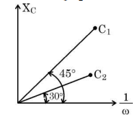
The figure shows the variation of capacitive reactance (X꜀) of two ideal capacitors of capacitances C₁ & C₂ with the reciprocal of angular frequency (1/ω) of ac source. The value of C₁/C₂ is
[1 Mark] Diagram 1 – CBSE Class 12 PCM Physics 2026 Set 2 Solutions
  • (A) 1/√3
  • (B) 2
  • (C) √3
  • (D) 1/2
Explanation: Capacitive reactance X꜀ is given by X꜀ = 1 / (ωC). When we plot X꜀ against 1/ω, the slope of the line is 1/C. Given two capacitors C₁ and C₂ with reactance lines, the ratio of their slopes will be C₂/C₁. Hence, the ratio C₁/C₂ equals the inverse of the ratio of slopes from the graph. Using the given data from the figure, the ratio C₁/C₂ is found to be 1/√3.
Question 12. A magnet held vertically, with its north pole down is dropped along the axis of a closed solenoid placed vertically on a table. If the observer looks down from the top,
[1 Mark]
  • (A) the induced current will flow in the anticlockwise direction
  • (B) the induced current will flow in the clockwise direction
  • (C) the magnet will fall with a constant velocity
  • (D) no induced current will flow in the solenoid
Explanation: As the north pole of the magnet moves down through the solenoid, it causes a change in the magnetic flux through the solenoid loops. According to Lenz's law, the induced current will flow in such a direction as to oppose the change in flux. Since the magnet's North pole is moving downwards, the solenoid will induce a magnetic field that opposes this motion by producing a North pole at the top. This results in an induced current flowing in the anticlockwise direction when viewed from above.
Question 13.

An electromagnetic wave is propagating along x-axis. At any instant, the phase difference (in radian) between the electric field (𝐄⃗) and the magnetic field (𝐁⃗) associated with the wave is

[1 Mark]
  • (A) π/4
  • (B) zero
  • (C) π/2
  • (D) π
Explanation: In an electromagnetic wave, the electric field (E) and magnetic field (B) oscillate perpendicular to each other and to the direction of wave propagation, but they are in phase. That means there is no phase difference between E and B fields; they reach their maximum and zero values simultaneously. Therefore, the phase difference between the electric and magnetic fields at any instant is zero.
Question 14.

In Bohr model of hydrogen atom, the electron makes a transition from n = 5 to n = 1 state. As a result, a photon of wavelength λ is emitted in the process. The wavelength of the photon emitted when an electron makes a transition from energy level n = 5 to n = 2 will be

[1 Mark]
  • (A) 8/7λ
  • (B) 24/7 λ
  • (C) 16/7λ
  • (D) 32/7 λ
Explanation: According to Bohr's model, the wavelength λ is related to the difference in energy levels by 1/λ = R_H (1/n_f^2 - 1/n_i^2). Given that the wavelength for the transition from n=5 to n=1 is λ, we have 1/λ = R_H (1/1^2 - 1/5^2) = R_H (1 - 1/25) = R_H (24/25). For transition n=5 to n=2, the wavelength λ' is given by 1/λ' = R_H (1/2^2 - 1/5^2) = R_H (1/4 - 1/25) = R_H (25/100 - 4/100) = R_H (21/100). Taking the ratio λ'/λ = (1/λ) / (1/λ') = (24/25) / (21/100) = (24/25) * (100/21) = 2400/525 = 24/7. Therefore, the wavelength for the transition from n=5 to n=2 is (24/7) times λ.
Question 15.

Assertion (A): On increasing the intensity of incident light of frequency (ν > ν₀) on a photosensitive surface, the photocurrent increases. Reason (R): The stopping potential for a photosensitive surface increases with increase of frequency (ν > ν₀) of incident light.

[1 Mark]
  • (A) Both Assertion (A) and Reason (R) are true and Reason (R) is the correct explanation of Assertion (A)
  • (B) Assertion (A) is true, but Reason (R) is false
  • (C) Assertion (A) is false and Reason (R) is also false
  • (D) Both Assertion (A) and Reason (R) are true, but Reason (R) is not the correct explanation of Assertion (A)
Explanation: The assertion is true because, for a given frequency above the threshold frequency, increasing the intensity of incident light increases the number of emitted electrons, thereby increasing the photocurrent. The reason is also true because the stopping potential depends on the frequency of incident light and increases with frequency. However, the stopping potential is independent of intensity, so the reason given does not correctly explain why the photocurrent increases with intensity. Hence, both A and R are true, but R is not the correct explanation for A.
Question 16.

Assertion (A): On forward biasing a p-n junction diode, the height of the barrier potential increases. Reason (R): In forward biasing of a p-n junction diode, the direction of the applied voltage is in the same direction as the built-in potential.

[1 Mark]
  • (A) Both Assertion (A) and Reason (R) are true and Reason (R) is the correct explanation of Assertion (A)
  • (B) Both Assertion (A) and Reason (R) are true, but Reason (R) is not the correct explanation of Assertion (A)
  • (C) Assertion (A) is true, but Reason (R) is false
  • (D) Assertion (A) is false and Reason (R) is also false
Explanation: In forward biasing of a p-n junction diode, the external voltage applied is opposite to the built-in potential's direction, which reduces the barrier potential height. Therefore, the barrier potential decreases, not increases, on forward biasing. Also, the applied voltage is in the opposite direction to the built-in potential, so both Assertion (A) and Reason (R) are false.
Question 17. Assertion (A): Light added to light can produce darkness. Reason (R): When two coherent light waves interfere, there is darkness at position of destructive interference.
[1 Mark]
  • (A) Both Assertion (A) and Reason (R) are true and Reason (R) is the correct explanation of Assertion (A)
  • (B) Both Assertion (A) and Reason (R) are true, but Reason (R) is not the correct explanation of Assertion (A)
  • (C) Assertion (A) is true, but Reason (R) is false
  • (D) Assertion (A) is false and Reason (R) is also false
Explanation: Light behaves like a wave and when two coherent light waves interfere, they can produce areas of constructive interference (bright) and destructive interference (dark). The darkness occurs due to destructive interference, where the two light waves cancel each other out. Therefore, light added to light can produce darkness, and this happens at the positions of destructive interference when two coherent waves overlap.
Question 18.

Assertion (A): Two electric heaters of power P₁ and P₂ (P₁ > P₂) are joined in series across a dc source of voltage V. The power consumed by the combination will be less than that consumed by P₁ when connected across the same source. Reason (R): The power consumed by an electric device when connected to a dc source of voltage V is proportional to its resistance.

[1 Mark]
  • (A) Assertion (A) is true, but Reason (R) is false
  • (B) Both Assertion (A) and Reason (R) are true and Reason (R) is the correct explanation of Assertion (A)
  • (C) Assertion (A) is false and Reason (R) is also false
  • (D) Both Assertion (A) and Reason (R) are true, but Reason (R) is not the correct explanation of Assertion (A)
Explanation: Assertion (A) is true because when two heaters (with resistances corresponding to power P₁ and P₂) are connected in series across the same voltage source, the total resistance increases, resulting in a lower current and, therefore, less power consumed by the combination compared to the power consumed by the single heater P₁ alone connected across the same voltage. The Reason (R) is also true in the sense that power consumed by a device is related to its resistance, but it is not proportional to resistance when voltage is constant; in fact, power P = V² / R, so power is inversely proportional to resistance, not proportional. Therefore, Reason (R) does not correctly explain Assertion (A).

Section C

Question 19.

Write two points of difference between intrinsic and extrinsic semiconductors.

[2 Marks]
Answer: (a) Intrinsic semiconductors are pure semiconductors without any significant impurity, and their conductivity depends only on temperature. (b) Extrinsic semiconductors are doped with impurities to increase conductivity; they can be of two types: n-type (doped with pentavalent atoms) and p-type (doped with trivalent atoms).
Key Points: Intrinsic semiconductors are pure and conductivity depends on temperature - Extrinsic semiconductors are doped with impurities to enhance conductivity - Extrinsic semiconductors are classified as n-type or p-type depending on the dopant
Question 20.

Find ratio (λₐ/λₚ) of the de Broglie wavelength λₐ and λₚ associated respectively with an alpha particle and a proton,
(i) if they are moving with the same kinetic energy.
(ii) just after they are accelerated through the same potential difference.

[2 Marks]
Answer: (i) When the alpha particle and proton have the same kinetic energy (K), kinetic energy K = (1/2)m v2
We have v = sqrt(2K/m). The de Broglie wavelength λ = h/mv = h/(m*sqrt(2K/m)) = h/sqrt(2Km). So, λ is inversely proportional to sqrt(m).
Therefore, (λₐ/λₚ) = sqrt(mₚ/mₐ)
Since mₐ = 4 mₚ (alpha particle has 2 protons and 2 neutrons),
(λₐ/λₚ) = sqrt(mₚ/4 mₚ) = 1/2

(ii) When accelerated through the same potential difference V, kinetic energy gained K = qV
For alpha particle, charge qₐ = 2e; For proton, qₚ = e
Then Kₐ = 2eV, Kₚ = eV
Velocity v = sqrt(2K/m). So,
λ = h/(m v) = h/(m sqrt(2K/m)) = h/sqrt(2mK)
Therefore, (λₐ/λₚ) = sqrt(mₚ qₚ / mₐ qₐ) = sqrt(mₚ e / 4 mₚ * 2 e) = sqrt(1 / 8) = 1/(2 sqrt(2))
Key Points: de Broglie wavelength λ = h/p - For same kinetic energy λ inversely proportional to sqrt(mass) - For same potential difference λ depends on both mass and charge through kinetic energy
Question 21.

A ray of light in air is incident at angle ∠i on a face of an equilateral glass prism and is refracted through the prism. As ∠i is varied, it is observed that the ray undergoes minimum deviation, when the ∠i is three-fourth of the angle of the prism. Calculate the speed of light in the prism.

[2 Marks]
Answer: Given: Angle of prism, A = 60deg since it is an equilateral prism. The angle of incidence at minimum deviation, i = 3/4 * A = 3/4 * 60 = 45deg.
At minimum deviation: Angle of incidence i = angle of emergence e, and angles of refraction r1 = r2 = r.
Using prism angle relation, r1 + r2 = A, so 2r = 60 => r = 30deg.
Using Snell's law at first face, n = sin i / sin r = sin 45 / sin 30 = (0.7071) / (0.5) = 1.414.
Refractive index, n = speed of light in air / speed of light in prism => v = c / n = 3 * 108 m/s / 1.414 = 2.12 * 108 m/s.
Answer: Speed of light in the prism is 2.12 * 108 m/s.
Key Points: Angle of incidence at minimum deviation is 3/4 of prism angle - Use Snell's law n = sin i / sin r - Calculate speed of light in prism v = c / n
Question 22.

A heating element using nichrome is connected to a 220 V supply. Initially it draws a current of 2.9 A. After some time, the current attains a steady value of 2.5 A. Find the steady temperature of the heating element if the room temperature is 27 °C. The temperature coefficient of resistance of nichrome is 1.7 × 10⁻⁴ °C⁻¹.

[2 Marks]
Answer: Given:
Voltage, V = 220 V
Initial current, I1 = 2.9 A
Final current, I2 = 2.5 A
Room temperature, T1 = 27 degC
Temperature coefficient of resistance, alpha = 1.7 * 10^-4 degC^-1

Step 1: Calculate initial resistance, R1 = V/I1 = 220/2.9 = 75.86 ohms
Step 2: Calculate final resistance, R2 = V/I2 = 220/2.5 = 88 ohms
Step 3: Use formula for resistance change with temperature:
R2 = R1 * [1 + alpha * (T2 - T1)]
=> 88 = 75.86 * [1 + 1.7 * 10^-4 * (T2 - 27)]
=> (88/75.86) - 1 = 1.7 * 10^-4 * (T2 - 27)
=> 0.16 = 1.7 * 10^-4 * (T2 - 27)
=> T2 - 27 = 0.16 / (1.7 * 10^-4) = 941.18 degC
=> T2 = 27 + 941.18 = 968.18 degC

Therefore, the steady temperature of the heating element is approximately 968 degC.
Key Points: Calculate initial resistance using V and initial current - Calculate final resistance using V and final current - Use resistance and temperature relation to find final temperature
Question 23.

A 5 cm long pencil is placed along the principal axis of a concave mirror of focal length 20 cm such that its nearest end is at a distance of 25 cm from the mirror. Calculate the length of the image of the pencil.

[2 Marks]
Answer: Given: Length of pencil, AB = 5 cm, Object distance of nearest end, u = -25 cm (since object is in front of the mirror), Focal length, f = -20 cm (concave mirror focal length is negative).
Step 1: Calculate image distance v for point A using mirror formula 1/f = 1/v + 1/u.
=> 1/v = 1/f - 1/u = 1/(-20) - 1/(-25) = -1/20 + 1/25 = (-5 + 4)/100 = -1/100.
=> v = -100 cm.
Step 2: Now object distance for point B = u + length of pencil = -25 - 5 = -30 cm.
Calculate image distance v' for point B: 1/f = 1/v' + 1/u'.
=> 1/v' = 1/f - 1/u' = 1/(-20) - 1/(-30) = -1/20 + 1/30 = (-3 + 2)/60 = -1/60.
=> v' = -60 cm.
Step 3: Length of image = |v'| - |v| = 100 cm - 60 cm = 40 cm.
Therefore, the length of the image of the pencil is 40 cm.
Key Points: Use of mirror formula 1/f = 1/v + 1/u - Calculation of image positions for both ends of the pencil - Length of the image = difference between image distances
Question 24.

In a Young's double-slit experiment, a beam of light consisting of two wavelengths 500 nm and 600 nm is used. The interference fringes are observed at a screen placed 1.8 m away from the plane of slits (slit separation 0.3 mm). Calculate the least distance from the central maximum where the bright fringes due to both the wavelengths coincide.

[2 Marks]
Answer: In Young's double slit experiment, bright fringes occur at positions x = (m * lambda * D) / d, where m = 0,1,2,..., lambda is the wavelength, D is distance to screen, and d is slit separation.
Given: lambda1 = 500 nm = 500 * 10^-9 m, lambda2 = 600 nm = 600 * 10^-9 m, D = 1.8 m, d = 0.3 mm = 0.3 * 10^-3 m.
The bright fringes of both wavelengths coincide where their fringe positions are equal:
(m * lambda1 * D) / d = (n * lambda2 * D) / d => m * lambda1 = n * lambda2
=> m / n = lambda2 / lambda1 = 600 / 500 = 6 / 5
So, the smallest integers m and n satisfying this are m=6, n=5.
Position of coincident bright fringes: x = (m * lambda1 * D) / d = (6 * 500 * 10^-9 * 1.8) / (0.3 * 10^-3) = 0.018 m = 1.8 cm.
Therefore, the least distance from the central maximum where bright fringes of both wavelengths coincide is 1.8 cm.
Key Points: Bright fringes position formula - Condition for coincident fringes m*lambda1 = n*lambda2 - Least common multiple approach to find smallest m and n - Calculation of distance x from the central maximum

Section D

Question 25.

(a) Consider the following nuclides:
¹²₆C, ¹⁹⁸₈₀Hg, ¹⁴₆C, ¹⁹⁷₇₉Au
Group them into isotopes and isotones.
(b) How does the size of a nucleus depend on its mass number A? Hence prove that the density of nucleus is a constant, independent of A, for all nuclei.

[3 Marks]
Answer: (a) Isotopes are nuclei with the same number of protons but different number of neutrons. Here, ¹²₆C and ¹⁴₆C are isotopes because both have 6 protons but different mass numbers 12 and 14 respectively. Isotones are nuclei with the same number of neutrons but different number of protons. For ¹²₆C, number of neutrons = 12 - 6 = 6; for ¹⁹⁸₈₀Hg, neutrons = 198 - 80 = 118; for ¹⁴₆C, neutrons = 14 - 6 = 8; for ¹⁹⁷₇₉Au, neutrons = 197 - 79 = 118. So, ¹⁹⁸₈₀Hg and ¹⁹⁷₇₉Au are isotones with 118 neutrons each.

(b) The size or radius R of a nucleus depends on its mass number A by the relation R = R₀ * A1/3, where R₀ is a constant approximately 1.2 fm (1.2 * 10-15 m). Since volume V of the nucleus is proportional to R3, we get V proportional to A. The mass of the nucleus is proportional to A as it equals A * mass of a nucleon. Therefore, density = mass/volume is proportional to A/A = constant. Hence, nuclear density is constant and independent of A for all nuclei. This means all nuclei have approximately the same density, which is very high compared to ordinary matter.
Key Points: Isotopes have same protons different neutrons - Isotones have same neutrons different protons - Nuclear radius R proportional to A to power 1/3 - Volume proportional to A - Density is constant independent of mass number A
Question 26.

(a) An electric field 𝐄⃗ = E₀ î exists in a region of space. Draw three equipotential surfaces in the region.
(b) Two point charges –q and +q are located at points (–a, 0, 0) and (a, 0, 0) respectively. Find the electrostatic potential at point (x, 0, 0) where x >> a.

[3 Marks]
Answer: (a) The electric field E = E₀ î is uniform and points along the x-axis. Equipotential surfaces are surfaces where the potential is constant. For a uniform electric field, equipotential surfaces are planes perpendicular to the direction of the field. Here, the three equipotential surfaces can be represented as three planes parallel to the yz-plane at different x-values. Each plane corresponds to a different constant potential V = -E₀ * x + C, where C is a constant.

(b) Two point charges are located at (-a, 0, 0) with charge -q and (a, 0, 0) with charge +q. The potential at point (x, 0, 0), where x >> a, is the algebraic sum of potentials due to each charge.
Potential V = k(-q) / |x + a| + k(q) / |x - a|, where k = 1 / (4 * pi * epsilon_0).
For x >> a, |x + a| approx x + a and |x - a| approx x - a.
Using binomial approximation: 1/(x + a) approx 1/x - a/x2 and 1/(x - a) approx 1/x + a/x2.
So, V = k[-q (1/x - a/x2) + q(1/x + a/x2)] = k[-q/x + q/x + a*q/x2 + a*q/x2] = k[2*a*q/x2].
Thus, potential at (x, 0, 0) for x >> a is V approx 2 * k * a * q / x2 which shows the potential decreases as 1/x2 far from the dipole.
Key Points: Equipotential surfaces in uniform field are planes perpendicular to field direction - Potential due to two point charges is sum of individual potentials - For dipole at large distance, potential varies as 1/x2 and equals 2 * k * a * q / x2
Question 27.

Name the electromagnetic waves which are used for
(i) detection of fractures in bones
(ii) physiotherapy
(iii) radar systems

Also write their wavelength range.

[3 Marks]
Answer: (i) X-rays are used for the detection of fractures in bones because they have high energy and can pass through soft tissues but are absorbed by bones, creating images.
(ii) Infrared rays are used in physiotherapy as they provide heat that helps in relaxing muscles and improving blood circulation.
(iii) Microwaves are used in radar systems due to their ability to travel long distances and reflect from objects, helping in detecting their position and speed.
Key Points: X-rays for bone fracture detection - Infrared rays in physiotherapy for heat treatment - Microwaves used in radar systems
Question 28.

(i) Define mutual inductance of a pair of coils. Write its SI unit.
(ii) A long solenoid of radius R and length L has n turns per unit length. A circular loop of radius r(<R) is placed inside at the centre of the solenoid such that its axis coincides with the axis of the solenoid. Obtain the mutual inductance of the solenoid and the loop.

[3 Marks]
Answer: (i) Definition of Mutual Inductance:
Mutual inductance of a pair of coils is defined as the property by which the magnetic flux through one coil changes when the current in the other coil changes. It is the ratio of the magnetic flux linked with one coil to the current in the other coil producing it. Its SI unit is Henry (H).

(ii) Derivation of Mutual Inductance between Solenoid and Loop:
Let the solenoid have length L, radius R, and n turns per unit length. The magnetic field inside the long solenoid is B = mu_0 * n * I where I is the current.
Since the circular loop of radius r (where r < R) is placed at the center of the solenoid and both axes coincide, the magnetic flux through the loop due to current I in solenoid is:
Flux, Phi = B * Area_of_loop = mu_0 * n * I * pi * r2
Mutual inductance M is defined by Phi = M * I => M = Phi / I = mu_0 * n * pi * r2

Hence, the mutual inductance of the solenoid and the circular loop placed inside it is M = mu_0 * n * pi * r2.
Key Points: Definition of mutual inductance - SI unit is Henry (H) - Formula derived for mutual inductance between solenoid and coaxial circular loop is M = mu_0 * n * pi * r squared
Question 29.

Two long straight parallel conductors A and B carrying steady currents Iₐ and I_b in the same direction are separated by a distance d. Deduce the expression for the force acting on length L of conductor B due to conductor A and show in figure. Write the expression for the force acting on length L of conductor A due to conductor B and show that it follows Newton’s third law.

[3 Marks]
Answer: (a) Force on conductor B due to conductor A: When current Iₐ flows in conductor A, it produces a magnetic field B_a at the location of conductor B. The magnitude of magnetic field produced by conductor A at distance d is B_a = (mu_0 / 2pi) * (Iₐ / d). This magnetic field acts perpendicular to conductor B. The force on length L of conductor B carrying current I_b in this magnetic field is given by F_ba = I_b * L * B_a = I_b * L * (mu_0 / 2pi) * (Iₐ / d) = (mu_0 / 2pi) * (Iₐ * I_b / d) * L. The direction of force is attractive since currents are in the same direction, so the force on B is towards A.
(b) Force on conductor A due to conductor B: Similarly, current I_b in conductor B produces magnetic field B_b at conductor A given by B_b = (mu_0 / 2pi) * (I_b / d). The force on length L of conductor A carrying current Iₐ is F_ab = Iₐ * L * B_b = (mu_0 / 2pi) * (I_b * Iₐ / d) * L. The direction of force on A is towards B.
Newton’s third law verification: The magnitudes of forces on A and B are equal, F_ab = F_ba, and they act in opposite directions. Hence, action and reaction forces are equal and opposite, confirming Newton’s third law.
This force causes the conductors to attract each other when currents are in the same direction.
Key Points: Magnetic field by conductor A at B - Force on conductor B due to A - Force on conductor A due to B - Forces are equal and opposite - Newton's third law verified
Question 30.

(a) State Bohr’s second postulate and mention its significance.
(b) Prove that, in Bohr model of hydrogen atom as principal quantum number n becomes large, the energy levels get closer and closer.

[3 Marks]
Answer: (a) Bohr's second postulate states that the angular momentum of an electron in a stationary orbit is quantised and is an integral multiple of h/2π, i.e., mvr = n(h/2π), where m is mass, v is velocity, r is radius, h is Planck's constant and n is principal quantum number. Its significance is that it explains the stability of atoms by restricting electrons to certain orbits without radiation and accounts for the discrete energy levels.
(b) According to Bohr's model, the energy of electron in nth orbit is E_n = -13.6 eV / n2. The difference between adjacent energy levels is ΔE = E_n+1 - E_n = -13.6 (1/(n+1)2 - 1/n2). For large n, 1/(n+1)2 ≈ 1/n2 - 2/n3. Therefore ΔE ≈ 13.6 * 2/n3. As n increases, ΔE approaches zero, meaning energy levels get closer and closer.
Key Points: Bohr's quantisation of angular momentum - Energy levels given by E_n = -13.6 / n^2 eV - Energy difference between levels decreases as n increases
Question 31.

(a) Explain the statement - “Current is a scalar although we represent current with an arrow.”
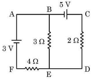
(b) Use Kirchhoff's rules to find the current through 3 Ω resistor in the circuit shown in the figure:
[3 Marks] Diagram 2 – CBSE Class 12 PCM Physics 2026 Set 2 Solutions
Answer: (a) Current is a scalar quantity because it has only magnitude and no inherent direction as a physical vector does. We represent current with an arrow to indicate its assumed direction of flow for analysis, but this arrow only shows the direction of positive charge flow conventionally. The actual current direction is defined by the circuit and does not affect its scalar nature.
(b) To find the current through the 3 Ω resistor using Kirchhoff's rules, first assign current directions and label currents I1, I2, I3. Apply Kirchhoff's current law (junction rule) at the junction where currents meet to establish relations between currents, for example I3 = I1 + I2. Then apply Kirchhoff's voltage law (loop rule) to loops in the circuit to write equations based on the sum of voltage drops and emfs being zero. Solve these simultaneous equations to find the value of current through the 3 Ω resistor. This method ensures conservation of charge and energy in the circuit.
Key Points: Current is scalar but represented with direction arrow for analysis - Kirchhoff's current law applies at junctions to relate currents - Kirchhoff's voltage law applies in loops to form equations to solve for unknown currents
Question 32.

Derive an expression for the magnetic field 𝐁⃗, due to a circular coil of N turns, each of radius r carrying current I, at a distance ‘x’ from the centre along its axis.

[3 Marks]
Answer: Derivation: Consider a circular coil of N turns, each of radius r, carrying current I. We want to find the magnetic field at a point P located at a distance x from the centre of the coil along its axis.
Using the Biot-Savart law, the magnetic field dB due to a small element of current is proportional to Idl sinθ/r2. For a circular coil, the magnetic field at point P on its axis is given by:
B = (μ0 N I r2)/(2 (r2 + x2)3/2)
where μ0 is the permeability of free space (4π * 10-7 T m/A).
Explanation: Each turn contributes a magnetic field at point P; all fields add up because the coil is closely wound.
At x = 0 (the centre of the coil), the expression reduces to B = (μ0 N I)/(2r), which is the known formula for magnetic field at the centre of the coil.
Key Points: Using Biot-Savart law - Formula for magnetic field on axis of coil - Final expression B = (μ0 N I r2)/(2 (r2 + x2)3/2), reduces to center formula

Section E

Question 33.

(a) What are coherent sources? Why are they necessary for observing stable interference pattern? Draw a graph showing the variation of intensity of light with the position on the screen in Young’s double-slit experiment.
(b) Find the intensity of light at a point on the screen when two interfering waves of the same intensity (I₀) have a path difference of
(i) λ/4 and (ii) λ/3.

[5 Marks]
Answer: (a) Coherent sources are sources of light which emit waves having the same frequency, constant phase difference and nearly equal amplitude. They are necessary to produce a stable and clear interference pattern because if the sources are not coherent, the phase difference between the waves keeps changing randomly, making the interference pattern unstable and unobservable.
In Young’s double-slit experiment, the intensity of light on the screen varies with the position, producing bright and dark fringes due to constructive and destructive interference. The graph of intensity versus position shows maxima (bright fringes) and minima (dark fringes) alternately. The intensity I at any point on the screen is given by I = 4I₀ cos2(φ/2), where φ is the phase difference related to the path difference.
Graph: A sinusoidal curve starting from maximum intensity, representing intensity variation with position along the screen showing bright and dark fringes.
(b) Given two waves of the same intensity I₀ and path difference Δ = (i) λ/4, (ii) λ/3.
The resultant intensity I = 4I₀ cos2(φ/2), where φ = (2π/λ) * path difference.
(i) For Δ = λ/4, φ = 2π * (1/4) = π/2.
Thus I = 4I₀ cos2(π/4) = 4I₀ * (sqrt(2)/2)2 = 4I₀ * 1/2 = 2I₀.
(ii) For Δ = λ/3, φ = 2π * (1/3) = 2π/3.
Thus I = 4I₀ cos2(π/3) = 4I₀ * (1/2)2 = 4I₀ * 1/4 = I₀.
Key Points: Definition of coherent sources - Importance of coherence for stable interference pattern - Formula and calculation of intensity with phase difference
Question 34.

(a) Draw a labelled ray diagram of a refracting telescope when it forms image of a distant object at infinity. Derive expression for its magnifying power.
(b) (i) In a telescope the objective has much larger aperture than the eye piece. Why?
(ii) Write two advantages of reflecting telescope over refracting telescope.

[5 Marks]
Answer: (a) A refracting telescope consists of two convex lenses, the objective lens (O) and the eyepiece lens (E). When used to view a distant object, the objective lens forms a real, inverted image near its focal point. The eyepiece lens is placed such that its focal point coincides with that of the objective lens, so the telescope is in normal adjustment and the final image is at infinity, which is comfortable for the eye.
Ray Diagram: Draw two convex lenses separated by the sum of their focal lengths (fo + fe). Parallel rays from a distant object strike the objective lens and converge to form an image at its focus. The eyepiece lens then makes the rays parallel again so the image is viewed at infinity.
Derivation of Magnifying Power (M): The angular magnification M is the ratio of the angle subtended by the image when viewed through the telescope to the angle subtended by the object when viewed with the naked eye.
Let angle subtended without telescope be θ and with telescope be θ'. Then M = θ' / θ.
For normal adjustment, the distance between the lenses is fo + fe.
Angular magnification M = fo / fe.
This means the magnifying power of the telescope is the ratio of the focal length of the objective lens to that of the eyepiece lens.

(b)(i) The objective lens has a much larger aperture than the eyepiece because a larger aperture collects more light from the distant object, making the image brighter and clearer. The eyepiece only magnifies the image and does not need to collect much light.

(b)(ii) Two advantages of reflecting telescope over refracting telescope are:
1. Reflecting telescopes do not suffer from chromatic aberration because mirrors reflect all colors equally, unlike lenses which disperse light.
2. They are easier and cheaper to make in large sizes because large mirrors are easier to support than large lenses, making them suitable for very powerful telescopes.
Key Points: Refracting telescope uses objective and eyepiece lenses - Magnifying power is fo / fe - Objective has larger aperture to collect more light - Reflecting telescopes avoid chromatic aberration - Reflecting telescopes are easier and cheaper to make large
Question 35.

(a) Derive an expression for the capacitance of a parallel plate capacitor of plate area A and plate separation d with air present between the plates.
(b) Two air-filled capacitors of capacitances C₁ and C₂ are connected in parallel with a dc battery. After the capacitors are fully charged, a slab of dielectric constant K is inserted between the plates of each capacitor. How will the (i) charge on each capacitor and (ii) energy stored in the capacitor affected after the slab is introduced.

[5 Marks]
Answer: (a) A parallel plate capacitor consists of two conducting plates of area A separated by a distance d with air between them. When connected to a battery, the capacitor stores charge Q and develops a potential difference V between its plates. The capacitance C is defined as the charge stored per unit potential difference, C = Q/V. For air or vacuum as dielectric medium, the capacitance is given by the formula C = ε₀ * A / d, where ε₀ is the permittivity of free space.

(b) Two capacitors of capacitances C₁ and C₂ are connected in parallel to a dc battery and fully charged. When a dielectric slab of constant K is inserted between the plates of each capacitor at constant voltage (due to battery), the capacitance of each capacitor increases by a factor K, so capacitance becomes K * C₁ and K * C₂.

(i) Since the capacitors remain connected to the battery, the voltage across each capacitor remains the same. Charge on each capacitor Q = C * V. So, after inserting the dielectric, charge on capacitor 1 becomes Q₁' = K * C₁ * V and on capacitor 2 becomes Q₂' = K * C₂ * V. Hence, charge on each capacitor increases by factor K.

(ii) Energy stored in a capacitor is given by U = 1/2 * C * V2. Since capacitance increases to K * C, and voltage remains constant, energy stored becomes U' = 1/2 * K * C * V2. Therefore, energy stored in each capacitor increases by factor K after dielectric insertion.
Key Points: Capacitance of parallel plate capacitor C = ε₀A/d - Dielectric increases capacitance by factor K - With battery connected, voltage constant, charge and energy increase by factor K
Question 36.

(a) An electric field 𝐄⃗ is established across the ends of a cylindrical conductor of length L and area of cross-section A. Discuss how electrons attain an average velocity, independent of time. Hence, obtain a relation between current in the conductor and this ‘average velocity’ of electrons.

(b) (i) This ‘average velocity’ is found be few mm/s for currents in range of a few amperes. How then is current established almost the instant a circuit is closed ?

(ii) Two copper wires having their radii in the ratio of 3 : 2 are connected in series across a battery. Find the ratio of the drift velocities of the electrons in the wires.

[5 Marks]
Answer: (a) When an electric field 𝐄⃗ is applied across a conductor, free electrons experience a force pointing opposite to the field direction. Due to many collisions with ions in the conductor, they do not continuously accelerate but reach an average steady velocity called drift velocity (vd), which is constant and independent of time.
The current (I) in the conductor is given by I = nAe vd, where n is the number density of free electrons, e is the charge of an electron, A is the cross-sectional area, and vd is the average drift velocity.
(b)(i) Although the drift velocity is very slow (few mm/s), the electric field propagates through the conductor nearly at the speed of light. This rapid propagation causes electrons throughout the conductor to start drifting almost simultaneously, so current is established almost instantly when the circuit is closed.
(b)(ii) In series connection, current I is same through both wires. Let r1 and r2 be radii of wires with ratio 3:2.
Cross-sectional areas, A1 = π r12, A2 = π r22 so ratio A1 : A2 = 9 : 4.
Using I = n e A vd and same I, n, e, we get vd1 A1 = vd2 A2 => vd1/vd2 = A2/A1 = 4/9.
Thus, the ratio of drift velocities is 4 : 9.
Key Points: Constant average drift velocity due to collisions - Current I = n e A v_d relation - Electric field propagates rapidly establishing current instantly - Same current in series wires results in inverse ratio of drift velocities to cross-sectional areas
Question 37.

(a) A series combination of L, C and R is connected to an a.c. source. Using a phasor diagram, derive an expression for the impedance of the circuit and phase difference between V and I.

(b) Under what conditions the

(i) impedance of the circuit is minimum ?

(ii) Wattless current flows in the circuit ?

[5 Marks]
Answer: (a) Consider a series LCR circuit connected to an a.c. source. Let R be the resistance, L inductance and C capacitance. Let the applied voltage be V and current be I.
The voltage across R is VR = I R, which is in phase with current I.
The voltage across inductor L is VL = I XL where XL = 2 pi f L, and it leads the current by 90deg.
The voltage across capacitor C is VC = I XC where XC = 1 / (2 pi f C), and it lags the current by 90deg.
In the phasor diagram, VR is along the reference axis (along I), VL is +90deg to I and VC is -90deg to I.
The net reactance voltage is VX = VL - VC = I (XL - XC).
Thus, the total voltage V = vector sum of VR and VX. The magnitude of voltage is V = I sqrt(R2 + (XL - XC)2).
Hence, the impedance Z = V / I = sqrt(R2 + (XL - XC)2).

Phase difference between voltage and current, phi = tan-1 ((XL - XC) / R). Voltage leads current if XL > XC and lags if XC > XL.

(b)
(i) The impedance of the circuit is minimum when the reactance terms cancel, i.e. XL = XC. This condition is called resonance.
(ii) Wattless current flows when the circuit current has zero phase difference with voltage across reactive elements, meaning current is purely reactive with no real power. This condition occurs when XL = XC, so circuit behaves like a pure resistance consuming no net power from the reactive parts.
Key Points: Phasor diagram shows voltage and current relations - Impedance formula Z = sqrt(R^2 + (X_L - X_C)^2) - Phase difference phi = tan^-1((X_L - X_C)/R) - Minimum impedance at resonance X_L = X_C - Wattless current flows at resonance when current is purely reactive
Question 38.

(i) With the help of a labelled diagram, explain the principle, construction and working of an a.c. generator.

(ii) Deduce an expression for the induced emf in the coil of the generator.

(iii) If T is the time period of the rotation of the coil, at what values of T in a cycle, the emf generator is maximum ?

[5 Marks]
Answer: (i) Principle: An a.c. generator works on the principle of electromagnetic induction which says that whenever a conductor moves in a magnetic field or the magnetic field around it changes, an emf is induced in the conductor.
Construction: It consists of a rectangular coil ABCD mounted on an axle so that it can rotate freely between the poles of a magnet producing a magnetic field B. The coil is connected to slip rings R and R' which rotate with the coil. Carbon brushes B and B' press on the slip rings to conduct current to the external circuit.
Working: When the coil rotates, the magnetic flux linked with the coil changes continuously. According to Faraday's law, this change induces an emf in the coil. The direction of emf changes every half rotation, resulting in alternating current in the external circuit.

(ii) Expression for induced emf:
If N is the number of turns of the coil, A is the area of each turn, B is the magnetic field strength and θ is the angle between the coil's normal and magnetic field at time t, then magnetic flux ϕ = N * B * A * cosθ.
If the coil rotates with angular velocity ω, then θ = ωt.
Induced emf E = - dϕ/dt = - d/dt (N * B * A * cosωt) = N * B * A * ω * sinωt.
Therefore, E = Emax * sinωt where Emax = N * B * A * ω.

(iii) Maximum emf in a cycle:
Emf is maximum when sinωt = ±1, i.e., ωt = 90deg, 270deg, 450deg,...
Since ω = 2π/T, maximum emf occurs at t = T/4, 3T/4, 5T/4, etc., i.e., at odd multiples of T/4 in each cycle.
Key Points: Principle of electromagnetic induction - Construction parts of a.c. generator - Working with rotating coil in magnetic field - Faraday's law for emf - Expression E = N * B * A * ω * sinωt - Maximum emf at ωt = odd multiples of 90deg or t = (2n+1)*T/4

Paper Details

CBSE Board Exam 2026

Class

Class 12 PCM

Subject

Physics

Year

2026

Set

Set 2

Other Years — Physics

2022 Set-1

2022 Set-2

2022 Set-3

2022 Set-4

2023 Set-1

2023 Set-2

2023 Set-3

2023 Set-4

2023 Set-5

2024 Set-1

2024 Set-2

2024 Set-3

2024 Set-4

2024 Set-5

2025 Set-1

2025 Set-2

2025 Set-4

2025 Set-5

2025 Set-6

2025 Set-7

2026 Set-1

2026 Set-2

2026 Set-3

2026 Set-4

2026 Set-5