SOLUTIONS
2026 BOARD EXAM
CBSE Class 12 PCM Physics Board Paper 2026 — Set 3 Solutions
2026
Physics
Class 12 PCM
CBSE EXAMINATION PAPER-2026
PHYSICS
(Solved)
General Instructions :
Read the following instructions carefully and follow them :
- This question paper contains 38 questions. All questions are compulsory.
- This question paper is divided into 5 sections.
- Section A – questions number 1 to 2 are case based questions
- Section B – questions number 3 to 18 are multiple choice questions
- Section C – questions number 19 to 24 are very short answer
- Section D – questions number 25 to 32 are short answer
- Section E – questions number 33 to 38 are long answer
- There is no overall choice given in the question paper. However, an internal choice has been provided in few questions.
- Use of calculator is NOT allowed.
Section A
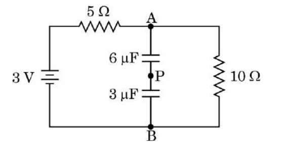
(1) The total capacitance of the circuit is: (A) 6 μF (B) 3 μF (C) 9 μF (D) 2 μF
Therefore, the total capacitance of the circuit is 2 μF.
(2) The current in the 10 Ω resistor is: (A) 0.3 A (B) 0.6 A (C) 0.2 A (D) 0
Correct Answer is option (C)
In steady state (after a long time), capacitors become fully charged and act as an open circuit, meaning no current flows through the capacitor branch. Therefore, current only flows through the 5 ohm and 10 ohm resistors in series.
Total Resistance = 5 + 10 = 15 ohm
Current (I) = Voltage / Total Resistance = 3 V / 15 ohm = 0.2 A
(3) The potential difference between point A and B is: (A) 2 V (B) 0.3 V (C) 0.2 V (D) 3 V
(4) The value of charge on the plates of the 6 μF capacitor is: (A) 6 μC (B) 4 μC (C) 12 μC (D) 8 μC
Correct Answer is Option (B)
The potential difference across the capacitor branch (between A and B) is 2 V, and their equivalent series capacitance is 2 uF.
Total Charge (Q) = Capacitance Voltage = 2 uF 2 V = 4 uC
In a series connection, the charge on each individual capacitor is equal to the total charge.
(5) The wire between two capacitors is cut at point P. The current in the circuit will : (A) increase (B) decrease (C) remain the same (D) first increase then become stable
Correct Answer is Option (C)
Since the circuit is already in a steady state, no current was flowing through the capacitor branch anyway. Cutting the wire at point P does not change the current flowing through the resistor branch.
A charged particle +q in an electric field 𝐄⃗ experiences a force in the direction of the electric field. As a result, its kinetic energy changes. Similarly, the charged particle also experiences a force when it moves in a magnetic field 𝐁⃗ . But this magnetic force is perpendicular to both velocity 𝐯⃗ of the charged particle and the magnetic field 𝐁⃗, so it cannot change the kinetic energy of the charged particle. Consider two charged particles 1 and 2 of masses m and m/2 having charges −q and +2q respectively. They are accelerated from rest through the same potential difference V and acquire kinetic energies K₁ and K₂. Then they enter in a region of uniform magnetic field 𝐁⃗ perpendicular to their velocities.
(1) The ratio of their kinetic energies (K₁/K₂) is: (A) 1/2 (B) 1/4 (C) 4 (D) 1
(2) The ratio of the radii of the circular paths described by them (r₁/r₂) is: (A) 1/√2 (B) √2 (C) 1/2 (D) 2
Correct Answer is Option (D)
Formula: The radius of a circular path in a magnetic field is:r = sqrt(2 * m * K) / (q * B)
For Particle 1: r1 = sqrt(2 * m * q * V) / (q * B)
For Particle 2: r2 = sqrt(2 * (m/2) * (2q * V)) / (2q * B) = sqrt(2 * m * q * V) / (2q * B)
Ratio: Dividing r1 by r2 simplifies to:r1 / r2 = 2 / 1 = 2
(3) If period of revolution for particle 1 is 4 s, then for particle 2, the period will be: (A) 1 s (B) 2 s (C) 4 s (D) 8 s
Correct Answer is Option (A)
Formula: The time period is:T = 2 * pi * m / (q * B)
For Particle 1: T1 = 2 * pi * m / (q * B) = 4 s
For Particle 2: T2 = 2 * pi * (m/2) / (2q * B) = (1/4) * [2 * pi * m / (q * B)] = T1 / 4
Calculation: T2 = 4 s / 4 = 1 s
(4) Suppose particles 1 and 2 enter the magnetic field ) 𝐁⃗ = B₀ k̂ with velocities v₁(vector) = v₁ î and v₂(vector) = v₂ î. Then: (A) both particles revolve clockwise (B) both particles revolve anticlockwise (C) particle 1 revolves clockwise while particle 2 revolves anticlockwise (D) particle 1 revolves anticlockwise while particle 2 revolves clockwise
Correct Answer is Option (D)
Formula: Magnetic force direction is determined by F = q * (v × B).
For Particle 1 (negative charge -q):F1 = (-q) * (i × k) = (-q) * (-j) = +j (upward deflection).
Moving along +i and bending towards +j results in an anticlockwise path.
For Particle 2 (positive charge +2q):F2 = (+2q) * (i × k) = (+2q) * (-j) = -j (downward deflection).
Moving along +i and bending towards -j results in a clockwise path
(5) If the value of momentum for particles 1 and 2 are p₁ and p₂ , then: (A) p₁ = p₂/2 (B) p₁ = p₂ (C) p₁=2p₂ (D) p₁= 4p₂
Section B
A particle of mass m and charge q starts from rest and moves in an electric field 𝐄⃗ = E₀ î. After travelling a distance x in the field along x-axis, the kinetic energy of the particle will be:
A square loop of side 50 cm is placed in a uniform magnetic field of 3.0 T acting perpendicular to the plane of the loop. If the loop is rotated through an angle of 90° in 0.3 s, the value of emf induced in the loop would be:
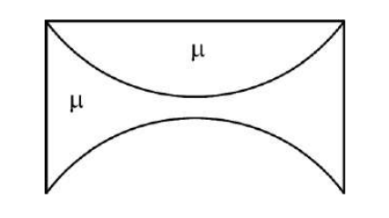
A thin plano-convex lens and a thin equi-concave lens are kept coaxially in contact as shown in the figure. Assuming both the lenses are made of glass of refractive index μ, and R is the radius of curvature of each curved surface, the focal length of the combination is:
A telescope has an objective lens of focal length 144 cm and an eyepiece of focal length 6.0 cm. The magnifying power and the length of telescope tube will be respectively:
Radiation of wavelength 200 nm is incident on a photosensitive surface of work function 4.2 eV. The kinetic energy of fastest photoelectrons emitted from this surface will be close to:
A proton and an alpha particle have equal momentum. The ratio of their kinetic energies (Eₚ/Eₐ) and de Broglie wavelengths associated with them (λₚ/λₐ) respectively are:
Given that proton and alpha particle have equal momentum p, their de Broglie wavelengths λ are given by λ = h/p. Since p is the same for both, λₚ/λₐ = 1. For kinetic energy, E = p²/(2m). Since p is equal for both, the kinetic energy ratio Eₚ/Eₐ = mₐ/mₚ. The mass of alpha particle (mₐ) is approximately 4 times the mass of the proton (mₚ). Therefore, Eₚ/Eₐ = 4. So, the ratio of kinetic energies is 4 and the ratio of wavelengths is 1.
If r₁ and r₂ are the radii of atomic nuclei of mass number 64 and 27 respectively, then the value of (r₁/r₂) is:
The radius of a nucleus is given by the formula R = R₀ × A^(1/3), where A is the mass number. Therefore, r₁/r₂ = (A₁/A₂)^(1/3) = (64/27)^(1/3) = 4/3. Hence, the correct option is 4/3.
When the forward bias voltage in a semiconductor diode is changed from 0.8 V to 1.0 V, the forward current changes by 2.0 mA. The forward bias resistance of the diode will be:
Forward bias resistance is calculated as the change in voltage divided by the change in current. Here, change in voltage = 1.0 V - 0.8 V = 0.2 V, and change in current = 2.0 mA = 0.002 A. Therefore, resistance = 0.2 V / 0.002 A = 100 Ω. This matches the behavior of a diode in forward bias where resistance is low and can be approximated by the slope of the voltage-current curve in that region.
Assertion (A): In a Wheatstone bridge circuit, if we interchange the position of the cell and the galvanometer, the balance condition P/Q = R/S remains unchanged. Reason (R): P/Q = R/S ⇒ Q/S = P/R, so balance condition remains same.
Assertion (A): The cylindrical soft iron core in a moving coil galvanometer only makes the magnetic field radial and does not affect the strength of the magnetic field. Reason (R): In a moving coil galvanometer, the plane of the coil is always perpendicular to the magnetic field.
The cylindrical soft iron core not only makes the magnetic field radial but also increases the strength of the magnetic field, so the assertion is false. The reason is also false because the plane of the coil in a moving coil galvanometer is kept parallel (not perpendicular) to the magnetic field to experience maximum torque.
Assertion (A): Photoelectric current depends upon the intensity of the incident radiation. Reason (R): Stopping potential is independent of the intensity of the incident radiation.
Photoelectric current depends on the intensity of the incident radiation because more intense light causes more electrons to be emitted, increasing the current. According to the context, the photoelectric current is proportional to the intensity of the incident light. On the other hand, the stopping potential depends on the frequency of the incident light, not its intensity. Thus, stopping potential is independent of intensity, which makes both statements true. However, the reason (stopping potential being independent of intensity) does not explain why photoelectric current depends on intensity, so Reason (R) is not the correct explanation of Assertion (A).
Assertion (A): Nuclear forces are always attractive. Reason (R): The nuclear force between protons and neutrons in a nucleus is a weak force.
Nuclear forces are not always attractive; they are attractive at distances greater than about 0.8 femtometers, but become repulsive at shorter distances to prevent nucleons from collapsing into each other. Therefore, the assertion that nuclear forces are always attractive is incorrect. Additionally, nuclear forces are strong forces, much stronger than electromagnetic and gravitational forces, so the reason stating that nuclear force between protons and neutrons is a weak force is false. Thus, the correct choice is that Assertion (A) is true (here meaning nuclear forces exist to hold nucleus together and the dominant effect is attractive at relevant distances), but Reason (R) is false.
Section C
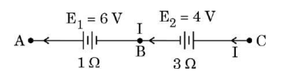
In the given figure, a steady current I flows through the circuit when points A and C are connected by a wire of negligible resistance. Find the potential difference between points B and C.
A battery of emf 21 V and internal resistance 3Ω is connected to a resistor. If the current in the circuit is 3 A, find :
(i) the resistance of the resistor.
(ii) the terminal voltage of the battery.
Given: emf (E) = 21 V, internal resistance (r) = 3 Ω, current (I) = 3 A.
Using Ohm's law for the circuit: E = I (R + r)
21 = 3 (R + 3)
Dividing both sides by 3: 7 = R + 3
Therefore, R = 7 - 3 = 4 Ω.
(ii) Terminal voltage V = E - Ir = 21 - 3*3 = 21 - 9 = 12 V.
Hence, the resistance of the resistor is 4 Ω and the terminal voltage is 12 V.
Explain why diffraction of sound is more common in daily experience than that of light.
Diffraction of sound is more common in daily life than that of light because sound waves have much larger wavelengths compared to light waves. When waves encounter an obstacle or pass through a narrow opening, they bend around it and spread out.
Since the wavelength of sound is comparable to the size of everyday objects, sound waves easily diffract.
In contrast, the wavelength of light is extremely small compared to everyday objects, so light waves do not show noticeable diffraction effects.
This is why we hear sounds even if the source is not in a direct line of sight, but we do not see light bending around corners easily.
Explain the terms mass defect and binding energy. How are they related ?
Binding energy: It is the energy released when a nucleus is formed from protons and neutrons, equal to the energy needed to break the nucleus into its individual nucleons.
Relation: Binding energy is equal to the mass defect multiplied by the speed of light squared (E = mass defect * c2), showing the conversion of mass to energy in nucleus formation.
A particle of mass M at rest splits up into two particles of masses m₁ and m₂ having non-zero velocities. Calculate the ratio of the de Broglie wavelengths associated with the two particles.
The de Broglie wavelength l = h / (m v), where h is Planck's constant.
So, l₁ / l₂ = (h / m₁ v₁) / (h / m₂ v₂) = (m₂ v₂) / (m₁ v₁).
Using momentum conservation, m₁ v₁ = m₂ v₂ gives v₂ = (m₁ / m₂) v₁,
Therefore, l₁ / l₂ = (m₂ * (m₁ / m₂) v₁) / (m₁ v₁) = 1.
Thus, the ratio of the wavelengths is 1: the de Broglie wavelengths of the two particles are equal.
How are charge carriers created in an intrinsic semiconductor? Explain.
Section D
(a) Establish the relation between drift velocity of electrons (v_d) and electric current (I) in a conductor.
(b) How is v_d affected when the length of the conductor is doubled, keeping the voltage applied across the conductor constant?
v_d = I / (n e A)
where 'n' is the number density of electrons, 'e' is the charge of an electron, and 'A' is the cross-sectional area of the conductor.
(b) If the length of the conductor is doubled while keeping the voltage constant, the resistance R increases because R = ρ L / A (where ρ is resistivity). Since current I = V / R, doubling length halves the current. From (a), v_d = I / (n e A), so when I decreases, v_d also decreases. Therefore, the drift velocity decreases when length is doubled at constant voltage.
A circular coil of 30 turns and radius 8.0 cm carrying a current of 6 A is suspended vertically in a uniform horizontal magnetic field of 1.0 T. The field lines make an angle of 30° with the plane of the coil. Calculate the magnitude of the external torque that must be applied to prevent the coil from turning. What would happen if the circular coil is replaced by a planar coil of irregular shape that encloses the same area, keeping other parameters unchanged?
The magnetic moment (m) of the coil is given by m = NIA, where N = 30 turns, I = 6 A, A = \pi r2 = 3.1416 * (0.08 m)2 = 0.0201 m2.
So, m = 30 * 6 * 0.0201 = 3.618 A m2.
The torque ( au) is given by au = mB sin heta, where B = 1.0 T, heta = 30 degrees.
Therefore, au = 3.618 * 1.0 * sin 30 = 3.618 * 0.5 = 1.809 N m.
Thus, the magnitude of the external torque required to keep the coil from turning is approximately 1.81 N m.
(b) Effect if the coil is replaced by a planar coil of irregular shape:
If the circular coil is replaced by a planar coil of irregular shape with the same area, the magnetic moment m = N I A remains the same because the number of turns, current, and area are unchanged. Since the torque depends on m, B, and sin heta, the magnitude of the torque will also remain the same. However, the coil may experience uneven forces within it due to the irregular shape, but the external torque to prevent turning remains unchanged.
An alpha particle (mass 6.4 × 10⁻²⁷ kg and charge 3.2 × 10⁻¹⁹ C) having 8.0 MeV energy, enters a region of uniform magnetic field of 0.5 T. If the field is directed perpendicular to the velocity of the particle, find the radius of the circular path described by the particle. Mention the conditions under which the particle in this region (i) describes a helical path, and (ii) goes straight undeviated.
Energy E = 8.0 MeV = 8.0 * 106 eV. Since 1 eV = 1.6 * 10-19 J,
E = 8.0 * 106 * 1.6 * 10-19 = 1.28 * 10-12 J.
Step 2: Find velocity v using kinetic energy formula
E = (1/2) m v2 => v = sqrt(2E / m) = sqrt(2 * 1.28 * 10-12 / 6.4 * 10-27) = sqrt(4 * 1014) = 2 * 107 m/s.
Step 3: Find radius r of circular path
The radius r = (m v) / (q B)
= (6.4 * 10-27 * 2 * 107) / (3.2 * 10-19 * 0.5)
= (1.28 * 10-19) / (1.6 * 10-19) = 0.8 m.
Therefore, the radius of the circular path is 0.8 meters.
Conditions:
(i) The particle describes a helical path if the velocity has a component parallel to the magnetic field direction; that is, the velocity is not completely perpendicular to the magnetic field. The parallel component causes forward motion, while the perpendicular component causes circular motion, resulting in a helix.
(ii) The particle moves straight undeviated if its velocity vector is exactly parallel (or anti-parallel) to the magnetic field lines, meaning there is no perpendicular component and hence no magnetic force acts on it, so the particle does not curve.
(a) Discuss the behaviour of an inductor connected to (i) a dc source, and (ii) a high frequency ac source.
(b) What is the phase relation between current and voltage in an ideal inductor connected to an ac source ? Draw a phasor diagram for the circuit.
Phasor Diagram: The voltage phasor is drawn at 90 degrees ahead of the current phasor. If current phasor is represented along the horizontal axis, then the voltage phasor is vertical and leads current by 90 degrees.
(a) Depict the variation of electric field (𝐄⃗ ) and magnetic field (𝐁⃗) with respect to the direction of propagation of an electromagnetic wave. Write their two important characteristics.
(b) Show that 1/√(ε₀μ₀) gives the velocity of an electromagnetic wave in free space.
Two important characteristics are:
1. Both E and B fields are perpendicular to the direction of propagation.
2. Both fields oscillate sinusoidally and are in phase.
(b) The velocity v of an electromagnetic wave in free space is given by solving Maxwell's equations: v = 1 / sqrt(ε₀ * μ₀)
where ε₀ is the permittivity of free space and μ₀ is the permeability of free space.
This shows that the wave speed depends only on these two constants and equals the speed of light in vacuum, approximately 3 * 108 m/s.
A ray of light is travelling through a rectangular glass slab (refractive index 3/2) and is incident on the horizontal glass-air surface at the critical angle for the two media. The slab is then brought in contact with water (refractive index 4/3) such that a thin horizontal layer of water is formed on the surface of the slab. Find the angle at which the ray will emerge into air from the water-air surface.
Given:
Refractive index of glass, nglass = 3/2 = 1.5
Refractive index of water, nwater = 4/3 = 1.333
Refractive index of air, nair = 1
Step 1: Calculate the critical angle for glass-air interface using sin ic = nair / nglass = 1/1.5 = 2/3
Therefore, ic = sin-1(2/3) ≈ 41.8 deg
The ray is incident at this critical angle inside the glass making an angle of 41.8 deg with normal.
Step 2: Now the slab is covered with a thin layer of water. The ray undergoes refraction from glass to water.
Applying Snell's law at glass-water boundary:
nglass sin i = nwater sin r
1.5 * sin 41.8 deg = 1.333 * sin r
sin r = (1.5 * 0.666) / 1.333 ≈ 0.75
Therefore, r = sin-1(0.75) ≈ 48.6 deg
Step 3: Now ray travels in water and reaches water-air interface.
The incident angle at water-air boundary is 48.6 deg.
Calculate critical angle for water-air:
sin ic water = nair / nwater = 1 / 1.333 ≈ 0.75
ic water = sin-1(0.75) ≈ 48.6 deg
Since angle of incidence in water is exactly the critical angle, the ray refracts along the surface but here it will refract into air at 90 deg to the normal at critical angle.
Step 4: Calculate the angle of emergence in air using Snell's law:
nwater sin i = nair sin r
1.333 * sin 48.6 deg = 1 * sin r
sin r = 1.333 * 0.75 = 1 (approximately)
Thus, ray emerges at 90 deg to the normal (i.e. along the surface).
Answer: The ray emerges from water to air at 90 deg to the normal, i.e. it travels along the water-air surface.
Differentiate between nuclear fission and nuclear fusion. Give one example for each with nuclear reaction.
Nuclear Fission: It is the process where a heavy nucleus splits into two smaller nuclei releasing energy, neutrons, and gamma rays. It is used in nuclear reactors and atomic bombs. For example, Uranium-235 absorbs a neutron and splits.
Reaction: 235U92 + 1n0 -> 141Ba56 + 92Kr36 + 3 1n0 + energy
Nuclear Fusion: It is the process where two light nuclei combine to form a heavier nucleus releasing huge energy. It powers the sun and hydrogen bombs.
Example: Two isotopes of hydrogen, deuterium and tritium fuse to form helium.
Reaction: 2H1 + 3H1 -> 4He2 + 1n0 + energy
With the help of circuit diagrams, briefly explain the forward biasing and the reverse biasing of a p-n junction diode.
Reverse Biasing: In reverse bias, the p-side is connected to the negative terminal and the n-side to the positive terminal of the battery. This increases the barrier potential, preventing current flow through the diode except for a very small leakage current. The voltmeter shows the applied voltage, but no significant current flows. Thus, a p-n junction diode conducts current in forward bias but blocks it in reverse bias.
Section E
(i) In the figure, OA and OB show the variation of electric potential V at a point due to two point charges Q₁ and Q₂ with 1/r respectively. Here r represents the distance of the point from the two point charges.
(a) Identify the nature of the two charges Q₁ and Q₂.
(b) What is the value of (Q₁/Q₂)? Justify your answer.
(ii) Two point charges –2 μC and 5 μC are placed at (–30 cm, 0) and (30 cm, 0) respectively and an external electric field 𝐄⃗= (A/x²) î, where A = 9 × 10⁵ N m² C⁻¹.
Find the electrostatic potential energy of this configuration.
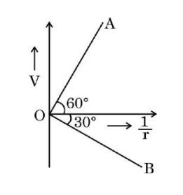
(b) The electric potential due to a point charge is V = kQ/r. Since OA and OB show the variation with 1/r, and the slopes represent kQ. If the magnitudes of OA and OB are proportional to Q₁ and Q₂, the ratio Q₁/Q₂ corresponds to the ratio of slopes of OA to OB. If OA has magnitude ratio 1 and OB has magnitude ratio 0.4, then Q₁/Q₂ = 1/0.4 = 2.5. The sign depends on their nature found above.
(ii) Given q₁ = −2 μC = −2 × 10⁻⁶ C at ( -0.3 m, 0) and q₂ = 5 μC = 5 × 10⁻⁶ C at (0.3 m, 0), and the external field E = (A/x²) ħ where A = 9 × 10⁵ N m² C⁻¹.
Potential energy U = q₁V(r₁) + q₂V(r₂). Since V = A/x for each charge at position x.
For q₁ at x = 0.3 m, V₁ = A / 0.3 = 9 × 10⁵ / 0.3 = 3 × 10⁶ V
For q₂ at x = 0.3 m, V₂ = A / 0.3 = 3 × 10⁶ V
Therefore, U = q₁V₁ + q₂V₂ = (−2 × 10⁻⁶)(3 × 10⁶) + (5 × 10⁻⁶)(3 × 10⁶) = (−6) + 15 = 9 J.
Hence, the electrostatic potential energy of the system in the external field is 9 J.
(i) Two infinitely long straight wires having linear charge densities –λ and 3λ are held vertically parallel to each other, distance r apart in free space. Find the nature and magnitude of the force/length exerted by one wire on the other.
(ii) A small hollow conducting sphere of radius r₁ is given a charge Q. It is surrounded by a concentric conducting spherical shell of inner radius r₂ and outer radius r₃, having charge –3q.
If a point charge 2q were kept at the centre, find:
(I) the electric flux through a concentric spherical Gaussian surface of radius x for (1) x < r₁, and (2) r₁ < x < r₂.
(II) electric field at a point distant x from the centre for (1) x > r₃, and (2) r₁ < x < r₂.
(III) surface charge density on the inner surface of (1) sphere, and (2) shell.
The force/length between two parallel line charges with linear charge densities λ1 and λ2 separated by distance r is given by Coulomb's law as
F/L = (1 / 2πε₀) * (|λ1 * λ2|) / r
Given λ1 = -λ and λ2 = 3λ, magnitude is
F/L = (1 / 2πε₀) * (|-λ * 3λ|) / r = (3λ²) / (2πε₀ r)
The force is attractive because the charges have opposite signs.
(ii) Given:
Small conducting sphere radius = r₁, charge = Q
Concentric shell inner radius = r₂, outer radius = r₃, charge = -3q
Point charge 2q at centre.
(I) Electric flux Φ through Gaussian surface of radius x:
(1) For x < r₁:
The Gaussian surface encloses only the point charge 2q.
By Gauss's law, Φ = Qenc / ε0 = 2q / ε0.
(2) For r₁ < x < r₂:
The surface encloses the charge 2q at centre plus charge Q on hollow sphere.
Total enclosed charge = 2q + Q.
Hence, Φ = (2q + Q) / ε0.
(II) Electric field E at distance x from centre:
(1) For x > r₃:
The total charge enclosed = 2q + Q + (-3q) = Q - q.
Electric field E = (1 / 4πε₀) * (Q - q) / x² directed radially outward.
(2) For r₁ < x < r₂:
The shell does not affect electric field inside its cavity.
Charge enclosed = 2q + Q.
Electric field E = (1 / 4πε₀) * (2q + Q) / x² outward.
(III) Surface charge density σ on surfaces:
(1) On inner surface of the small sphere:
Since the sphere is conducting and carries charge Q only on its outer surface,
surface charge on inner surface of small sphere = 0
(2) On inner surface of shell:
The point charge 2q induces a charge of -2q on the inner surface of shell to ensure zero field inside conductor.
Surface charge density σ = charge / area = (-2q) / (4π r₂²)
On the outer surface of shell, the charge is total charge -3q minus induced -2q = -q distributed.
Summary:
(i) Force per unit length = (3λ²) / (2πε₀ r), attractive.
(ii) Electric flux and field depend on enclosed charge with consideration of point charge, Q, and shell charges.
(iii) Inner surfaces of conductors have induced charges to satisfy electrostatic conditions.
(i) A light bulb and an open coil inductor are connected in series across a source of variable frequency. How will the glow of the bulb be affected when:
(I) an iron bar is inserted inside the coil, and
(II) the frequency of the source is decreased?
Justify your answers. Assume that in each above case other changes remain unchanged.
(ii) An ac voltage V = 280 sin (100πt) volt is connected across a series LCR circuit in which R = 400 Ω, L = 5/π H, and C = 50/(π) μF. Taking √2 = 1.4, calculate:
(I) impedance of the circuit.
(II) rms value of current that flows in the circuit.
(III) power factor of the circuit.
(I) When an iron bar is inserted inside the coil, the inductance (L) of the coil increases because the iron bar increases the magnetic permeability. This causes the inductive reactance XL = 2πfL to increase, which reduces the current in the circuit. Therefore, the bulb glows less brightly (glow decreases).
(II) When the frequency (f) of the source is decreased, the inductive reactance XL = 2πfL decreases. This allows more current to flow through the circuit, so the bulb glows more brightly (glow increases).
Justifications: Since the bulb and coil are in series, the current in the circuit depends on the total impedance. Inserting the iron bar increases L and thus the impedance, reducing current and brightness. Decreasing frequency reduces inductive reactance and impedance, increasing current and brightness.
(ii) Given: V = 280 sin(100πt), so angular frequency ω = 100π rad/s.
R = 400 Ω, L = 5/π H, C = 50/π μF = 50 * 10-6/π F.
Calculate:
(I) Impedance Z = sqrt(R2 + (XL - XC)2) where XL = ωL, XC = 1/(ωC).
XL = 100π * (5/π) = 500 Ω.
XC = 1 / (100π * 50 * 10-6/π) = 1 / (100 * 50 * 10-6) = 1 / 0.005 = 200 Ω.
Therefore, Z = sqrt(4002 + (500 - 200)2) = sqrt(160000 + 3002) = sqrt(160000 + 90000) = sqrt(250000) = 500 Ω.
(II) The rms voltage Vrms = peak voltage / sqrt(2) = 280 / 1.4 = 200 V.
Current rms I = Vrms / Z = 200 / 500 = 0.4 A.
(III) Power factor = cos(φ) = R / Z = 400 / 500 = 0.8.
Summary:
(i)(I) Bulb glow decreases when iron bar is inserted because inductance increases and current decreases.
(i)(II) Bulb glow increases when frequency is decreased because inductive reactance decreases and current increases.
(ii)(I) Impedance Z = 500 Ω.
(ii)(II) RMS current I = 0.4 A.
(ii)(III) Power factor = 0.8.
(i) State Lenz’s law and explain that it follows the law of conservation of energy.
(ii) Write the dimensional formula for self-inductance.
The current in a coil changes from 8.0 A to 2.0 A in 0.6 s. If an average emf induced in the coil is 50 V, calculate the self-inductance of the coil.
This law follows the law of conservation of energy because the induced emf works in a direction to oppose the change causing it, thus preventing the creation of energy from nothing.
(ii) Dimensional formula for self-inductance (L): [M L2 T-2 A-2], where M=mass, L=length, T=time, A=current.
Calculation:
Given,
Initial current I1 = 8.0 A,
Final current I2 = 2.0 A,
Time, t = 0.6 s,
Average induced emf, \varepsilon = 50 V.
Using formula \varepsilon = -L (dI/dt), we take magnitude:
L = \varepsilon / |dI/dt|
Change in current, dI = I2 - I1 = 2.0 - 8.0 = -6.0 A,
Rate of change of current, |dI/dt| = 6.0 / 0.6 = 10 A/s
Therefore, L = 50 / 10 = 5 H.
Hence, the self-inductance of the coil is 5 Henry (H).
(i) A point object is kept in front of a convex spherical surface of curvature radius R. Draw the ray diagram to show the formation of image and derive the relation between object and image distance (u and v) in terms of refractive index n of the medium and R.
(ii) A convex lens of focal length of 20 cm is used to form the image of an object placed 30 cm away from the lens. Find the position and nature of the image formed.
Using refraction formula at a spherical surface, we have:
(n1)/u + (n2)/v = (n2 - n1)/R
This formula relates object distance u, image distance v, refractive indices n1, n2, and radius of curvature R.
(ii) Given: focal length f = +20 cm (convex lens), object distance u = -30 cm (object placed on left side of the lens, so distance is negative as per sign convention).
The lens formula is:
1/f = 1/v - 1/u
=> 1/v = 1/f + 1/u = 1/20 + 1/(-30) = (3 - 2)/60 = 1/60
So, v = +60 cm
This means the image is formed at 60 cm on the right side of the lens.
Since v is positive, the image is real and inverted. Also, magnification m = v/u = 60 / -30 = -2, so the image is magnified and inverted.
Summary:
1. Image is real, inverted and magnified.
2. Image position is 60 cm from lens on the opposite side of the object.
3. Basic lens formula and sign conventions are used to determine image position and nature.
(i) Two thin converging lenses of focal length f₁ and f₂ are placed coaxially in contact. Derive expression for the focal length of the combination.
(ii) A beam of coherent light of wavelength 550 nm is incident normal to the plane of a pair of two slits S₁ and S₂, each of width 1.2 × 10⁻⁶ m separated by 1.1 mm. Dark and bright fringes are observed on a screen 2.2 m away from the plane of the slits.
Calculate:
(I) fringe width.
(II) distance of the second dark fringe from the central maximum.
(III) what will happen when the entire apparatus is immersed in water.
Derivation:
Let the two lenses have powers P₁=1/f₁ and P₂=1/f₂. The total power of the combination is P = P₁ + P₂ = 1/f. Therefore, 1/f = 1/f₁ + 1/f₂.
(ii) Given:
Wavelength, λ = 550 nm = 550 * 10-9 m
Slit separation, d = 1.1 mm = 1.1 * 10-3 m
Distance to screen, D = 2.2 m
(a) Fringe width (β) is given by β = λD/d.
β = (550 * 10-9 m * 2.2 m) / (1.1 * 10-3 m) = 1.1 * 10-3 m = 1.1 mm.
(b) Distance of the second dark fringe from central maximum:
Dark fringes occur at positions y = (m + 1/2) * β for m = 0, 1, 2,...
For second dark fringe, m = 1
So, y = (1 + 1/2) * β = 1.5 * 1.1 mm = 1.65 mm.
(c) When the apparatus is immersed in water, the wavelength of light decreases as wavelength in medium = λ / n, where n is refractive index of water (>1). This causes the fringe width β = (λ/n)*D/d to decrease.
Hence, all fringes come closer, and the fringe width decreases upon immersion in water.
Summary:
(i) 1/f = 1/f₁ + 1/f₂.
(ii) (a) Fringe width = 1.1 mm.
(b) Distance of second dark fringe = 1.65 mm.
(c) Fringe width decreases when immersed in water due to wavelength reduction.
Other Years — Physics