Zener Diode and Its Role in Voltage Regulation
Understanding Voltage Regulation and Its Importance
Fundamentals of Voltage Regulation Devices
A voltage regulator is an electronic component designed to maintain a steady voltage level regardless of fluctuations in input voltage or load conditions. Its primary function is to ensure that the output voltage remains stable, protecting sensitive electronic circuits from damage due to voltage variations. Voltage regulators are widely used in devices such as computers, power generators, and alternators to provide consistent power supply.
Voltage regulation is crucial because many electronic components require a fixed voltage to operate correctly. Without regulation, voltage spikes or drops could lead to malfunction or permanent damage.
Example: Consider a power supply that provides an input voltage varying between 12 V and 15 V. A voltage regulator can maintain the output voltage at a constant 5 V to power a microcontroller safely.
Characteristics and Operation of the Zener Diode
How the Zener Diode Maintains Constant Voltage
The Zener diode is a specialized silicon semiconductor device with a p-n junction engineered to operate reliably in reverse bias. Unlike a typical diode that blocks current in reverse bias, the Zener diode allows current to flow once the reverse voltage reaches a specific value known as the Zener voltage. At this point, the voltage across the diode remains nearly constant over a wide range of currents, making it ideal for voltage regulation.
When forward biased, the Zener diode behaves like a standard diode, allowing current to pass easily. However, in reverse bias, it stabilizes the voltage at its breakdown voltage, preventing voltage from rising above this level.
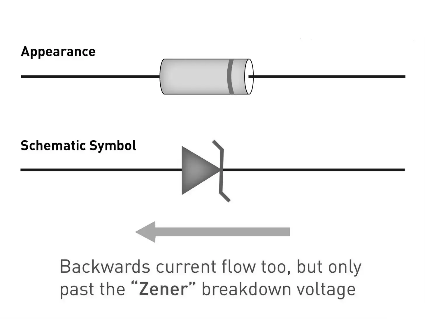
This image shows the appearance and schematic symbol of a Zener diode. It also explains that the Zener diode allows current to flow backward only when the voltage exceeds a certain level called the "Zener breakdown voltage." Step-by-step explanation for high school students: 1. The top part shows what a Zener diode looks like physically. 2. The middle part shows the schematic symbol used to represent a Zener diode in circuit diagrams. 3. The arrow points backward, explaining that current can flow in reverse through the Zener diode. 4. However, this reverse current only happens when the voltage is higher than the Zener breakdown voltage. 5. This feature allows the Zener diode to be used for voltage regulation and protection in electronic circuits.
Example: A Zener diode with a breakdown voltage of 6 V is connected in reverse bias. If the input voltage varies between 8 V and 12 V, the voltage across the diode remains stable at approximately 6 V, protecting the circuit from voltage fluctuations.
Implementing Zener Diode as a Voltage Regulator
Design and Functionality of Zener-Based Voltage Regulation Circuits
In practical voltage regulation circuits, a Zener diode is connected in reverse bias parallel to the load, with a series resistor placed before it to limit current. This resistor protects the diode by dropping excess voltage and controlling the current flowing through the diode and load.
The series resistor value \( R_S \) is calculated based on the difference between the input voltage \( V_L \), the Zener voltage \( V_Z \), and the load current \( I_L \) as:
\[ R_S = \frac{V_L - V_Z}{I_L} \]
This ensures that the Zener diode operates within its breakdown region, maintaining a constant output voltage equal to \( V_Z \) despite variations in input voltage or load current.
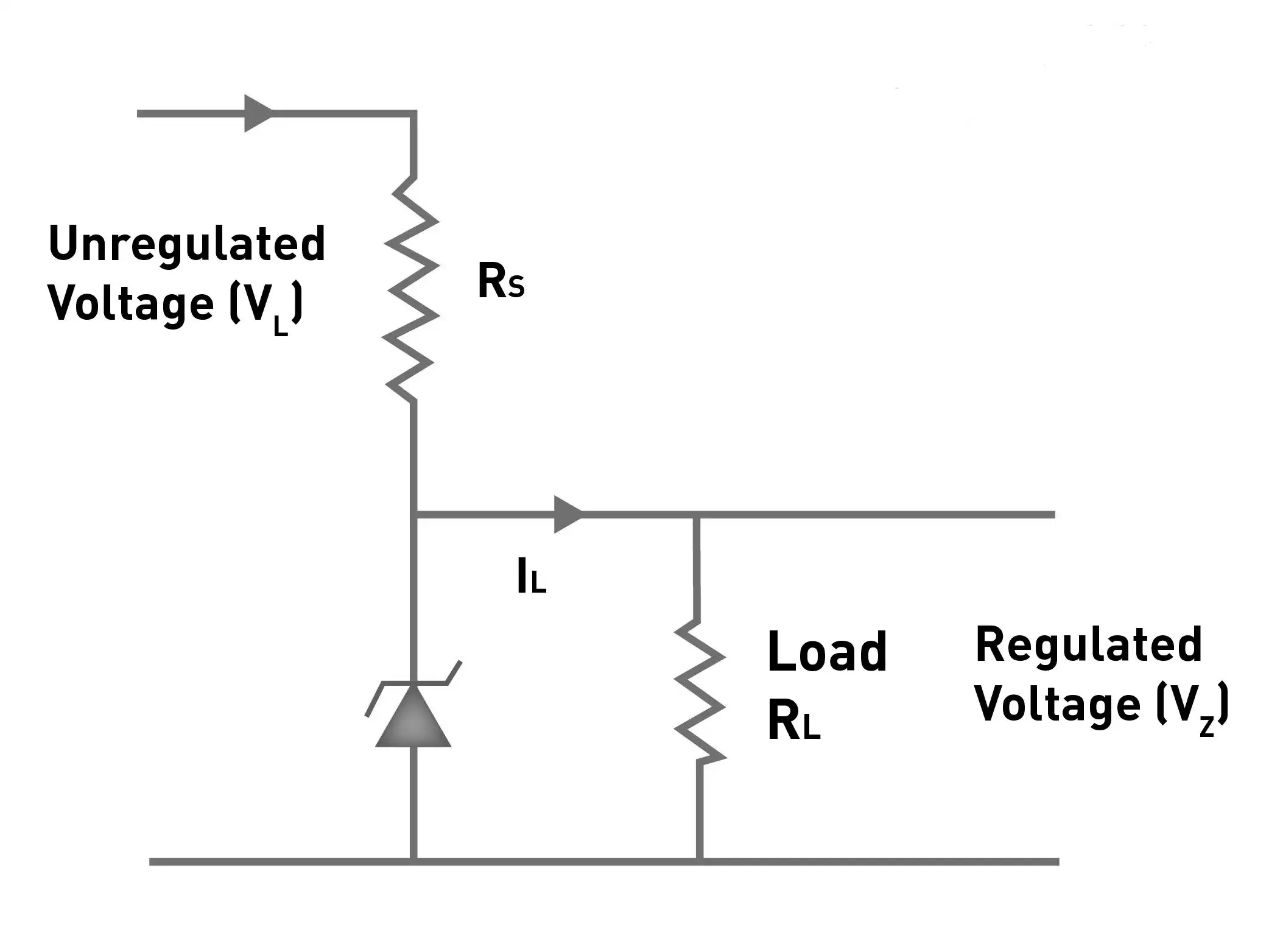
The image shows a simple voltage regulator circuit using a Zener diode. Step-by-step explanation for high school students: 1. The circuit takes an unregulated voltage (VL) as input. 2. Rs is a series resistor that limits the current flowing through the circuit. 3. The Zener diode is connected in parallel with the load resistor (RL). 4. The Zener diode maintains a constant voltage (VZ) across the load by adjusting the current (IL) flowing through it. 5. This keeps the voltage across the load stable and regulated, despite variations in the input voltage or load.
Given:
Load voltage, \( V_Z = 4.7 \text{ V} \)
Load current, \( I_L = 20 \text{ mA} = 0.02 \text{ A} \)
Maximum input voltage, \( V_L = 9 \text{ V} \)
Using the formula:
\[ R_S = \frac{V_L - V_Z}{I_L} = \frac{9 - 4.7}{0.02} = \frac{4.3}{0.02} = 215 \ \Omega \]
Thus, a resistor of approximately \( 215 \ \Omega \) should be used in series to ensure proper voltage regulation.
Summary Table for Quick Revision
Concept | Key Points |
|---|---|
Zener Diode | Operates in reverse bias; maintains constant voltage at breakdown voltage |
Voltage Regulator | Device that keeps output voltage steady despite input/load changes |
Series Resistor | Limits current through Zener diode; calculated by \( R_S = \frac{V_L - V_Z}{I_L} \) |
Zener Voltage (\( V_Z \)) | Voltage at which Zener diode breaks down and regulates voltage |
Load Current (\( I_L \)) | Current drawn by the load connected across the Zener diode |
Breakdown Region | Operating region where Zener diode maintains constant voltage |
Forward Bias | Diode conducts current like a normal diode |
Reverse Bias | Diode blocks current until breakdown voltage is reached |
Zener Breakdown | Sharp increase in reverse current at breakdown voltage without damage |
Voltage Stability | Output voltage remains constant despite input or load variations |
Glossary of Important Terms
Term | Definition |
|---|---|
Zener Diode | A diode designed to operate in reverse breakdown region to regulate voltage |
Voltage Regulator | Device that maintains a constant output voltage |
Breakdown Voltage | The voltage at which a diode begins to conduct in reverse bias |
Series Resistor | Resistor used to limit current in a voltage regulator circuit |
Forward Bias | Condition where diode allows current flow easily |
Reverse Bias | Condition where diode blocks current until breakdown |
Load Current | Current drawn by the device connected to the voltage regulator |
Zener Breakdown | Controlled breakdown in Zener diode allowing voltage regulation |
Voltage Stability | Ability to keep voltage constant despite changes |
Input Voltage | Voltage supplied to the voltage regulator circuit |
Frequently Asked Questions
What is the main purpose of a voltage regulator?
A voltage regulator ensures that the output voltage remains constant despite variations in input voltage or load conditions, protecting electronic devices from damage.
How does a Zener diode maintain a constant voltage?
When reverse biased, the Zener diode allows current to flow once the voltage reaches its breakdown voltage, keeping the voltage across it stable over a wide current range.
Why is a series resistor necessary in a Zener diode voltage regulator circuit?
The series resistor limits the current flowing through the Zener diode, preventing it from damage and ensuring proper voltage regulation.
How is the breakdown voltage of a Zener diode determined during manufacturing?
The breakdown voltage is set by controlling the doping concentration of the semiconductor material during the diode's fabrication process.
What happens to the output voltage if the input voltage varies within limits in a Zener diode regulator?
The output voltage remains nearly constant at the Zener voltage, as the diode adjusts its current to compensate for input voltage changes.