Comprehensive Guide to Zener Diodes: Operation, Characteristics, and Applications
Fundamentals and Historical Background of Zener Diodes
Understanding the Zener Diode and Its Unique Functionality
A Zener diode is a specially engineered semiconductor device designed to allow current flow not only in the forward direction like a typical diode but also in reverse once a specific voltage threshold is reached. This threshold, known as the Zener voltage, triggers a controlled breakdown in the diode's junction, enabling current to flow backward without damaging the device. This controlled reverse conduction is the hallmark of Zener diodes and is widely exploited in voltage regulation and protection circuits.
Origin and Definition of the Zener Diode
Developed with a high level of doping, Zener diodes are tailored to operate reliably in reverse bias conditions. They come with a range of breakdown voltages, often adjustable, to suit various electronic applications. The device is named after Clarence Melvin Zener, a physicist who first theorized the breakdown mechanism that these diodes utilize.
Historical Insight: Clarence Zener's Contribution
Clarence Melvin Zener, a theoretical physicist at Bell Labs, published a seminal paper in 1934 describing the electrical breakdown phenomenon in semiconductors, now known as the Zener effect. His work laid the foundation for the development of the Zener diode, which has become a critical component in modern electronics.
Mechanisms of Operation and Breakdown Phenomena in Zener Diodes
Reverse Bias Behavior and Breakdown Initiation
When a Zener diode is forward biased, it behaves similarly to a standard diode, allowing current to flow easily. However, under reverse bias, it initially permits only a minimal leakage current. As the reverse voltage approaches the diode's specified breakdown voltage, a sharp increase in current occurs, stabilizing at a level controlled by the external circuit. This controlled breakdown enables the diode to maintain a nearly constant voltage across it despite variations in current.
Understanding Avalanche Breakdown in Zener Diodes
Avalanche breakdown happens when the reverse voltage is sufficiently high to accelerate free electrons to energies that can knock loose additional electrons through collisions. This chain reaction rapidly multiplies charge carriers, causing a sudden surge in current. While this effect can damage ordinary diodes, Zener diodes are designed to endure this process safely. Avalanche breakdown typically occurs in Zener diodes with breakdown voltages exceeding approximately 6 volts.
Exploring the Zener Breakdown Effect
In contrast, Zener breakdown is a quantum mechanical effect that occurs at lower breakdown voltages, generally below 5.6 volts. Here, the intense electric field in the depletion region pulls electrons directly from their atomic bonds, creating a sudden increase in current without damaging the diode. This effect allows precise voltage regulation in low-voltage applications.
Comparing Avalanche and Zener Breakdown
While both breakdown mechanisms enable reverse conduction, the Zener effect is dominant at lower voltages and involves quantum tunneling, whereas avalanche breakdown occurs at higher voltages and involves impact ionization. Avalanche breakdown allows higher current flow but is less precise for voltage regulation compared to the Zener effect.
Example: Calculating Current in a Zener Diode Circuit
Consider a Zener diode with a breakdown voltage of \( 4.7 \text{ V} \) connected in reverse bias across a \( 12 \text{ V} \) supply through a \( 1 \text{ k}\Omega \) resistor. Calculate the current flowing through the diode once breakdown occurs.
Solution:
The voltage across the resistor is the supply voltage minus the Zener voltage:
\[ V_R = 12 \text{ V} - 4.7 \text{ V} = 7.3 \text{ V} \]
Using Ohm's law, the current through the resistor (and thus the diode) is:
\[ I = \frac{V_R}{R} = \frac{7.3 \text{ V}}{1000 \ \Omega} = 7.3 \text{ mA} \]
This current is maintained by the Zener diode to keep the voltage across it constant at \( 4.7 \text{ V} \).
Symbolism, Characteristics, and Practical Uses of Zener Diodes
Recognizing the Zener Diode Symbol and Packaging
The Zener diode symbol resembles that of a standard diode but includes distinctive perpendicular lines at the cathode end, indicating its unique breakdown behavior. These diodes are available in various packages, from small glass enclosures for low-power applications to surface-mount devices for compact circuits.
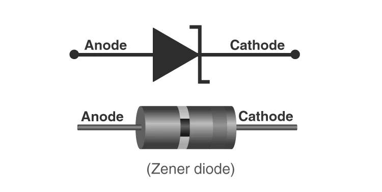
Standard circuit symbol representing a Zener diode
Voltage-Current Characteristics of Zener Diodes
The V-I curve of a Zener diode is divided into forward and reverse regions. In forward bias, it behaves like a typical diode, allowing current to increase exponentially with voltage. In reverse bias, the diode blocks current until the breakdown voltage is reached, after which the current rises sharply while the voltage remains nearly constant.
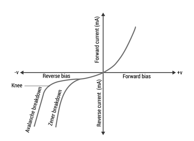
Typical V-I characteristics of a Zener diode showing forward and reverse behavior
Key Specifications of Zener Diodes
Important parameters to consider when selecting a Zener diode include:
Breakdown Voltage (Vz): The voltage at which the diode enters breakdown, ranging from about 2.4 V to over 200 V.
Maximum Current (Iz max): The highest current the diode can safely conduct at breakdown voltage.
Minimum Current (Iz min): The minimum current required to maintain the breakdown condition.
Power Rating: The maximum power dissipation, calculated as \( P = V_z \times I_z \).
Temperature Stability: Diodes near 5 V exhibit optimal voltage stability with temperature changes.
Voltage Tolerance: Typically ±5% variation from the nominal breakdown voltage.
Zener Resistance (Rz): The dynamic resistance in the breakdown region affecting voltage regulation precision.
Practical Applications of Zener Diodes
Zener diodes are widely used in electronic circuits for:
Voltage Regulation: Acting as shunt regulators, they maintain a constant output voltage across loads by operating in the breakdown region.
Overvoltage Protection: Protecting sensitive components by clamping voltage spikes to safe levels.
Waveform Clipping: Modifying AC signals by limiting voltage peaks in clipping circuits.
Example: Designing a Voltage Regulator Using a Zener Diode
Design a voltage regulator circuit to provide a stable \( 9 \text{ V} \) output from a \( 15 \text{ V} \) supply using a Zener diode with \( V_z = 9 \text{ V} \) and a load current of \( 20 \text{ mA} \). Calculate the series resistor value.
Solution:
The resistor must drop the excess voltage and supply the Zener current. Assume a Zener current \( I_z = 5 \text{ mA} \) for regulation.
Total current through resistor:
\[ I_R = I_L + I_z = 20 \text{ mA} + 5 \text{ mA} = 25 \text{ mA} \]
Voltage across resistor:
\[ V_R = 15 \text{ V} - 9 \text{ V} = 6 \text{ V} \]
Resistor value:
\[ R = \frac{V_R}{I_R} = \frac{6 \text{ V}}{0.025 \text{ A}} = 240 \ \Omega \]
A standard resistor of \( 240 \ \Omega \) will ensure proper voltage regulation.
Quick Reference: Essential Zener Diode Parameters
Parameter | Description | Typical Range |
|---|---|---|
Breakdown Voltage (Vz) | Voltage at which diode enters breakdown | 2.4 V to 200 V (up to 1 kV in special cases) |
Maximum Current (Iz max) | Maximum current at breakdown voltage | 200 μA to 200 A |
Minimum Current (Iz min) | Minimum current to maintain breakdown | Varies by diode type |
Power Rating | Maximum power dissipation | Varies; calculated as \( V_z \times I_z \) |
Voltage Tolerance | Allowed variation in breakdown voltage | ±5% |
Zener Resistance (Rz) | Dynamic resistance in breakdown region | Low ohms |
Temperature Stability | Voltage stability with temperature changes | Best near 5 V |
Glossary of Key Terms Related to Zener Diodes
Term | Definition |
|---|---|
Zener Diode | A diode designed to operate in reverse breakdown region for voltage regulation. |
Zener Voltage (Vz) | The specific reverse voltage at which the diode breaks down and conducts. |
Breakdown | The voltage point where the diode starts conducting in reverse bias. |
Avalanche Breakdown | Breakdown caused by impact ionization at high reverse voltages. |
Zener Breakdown | Quantum mechanical breakdown occurring at lower voltages due to strong electric fields. |
Forward Bias | Condition where diode allows current flow in the forward direction. |
Reverse Bias | Condition where diode blocks current until breakdown voltage is reached. |
Leakage Current | Small current flowing through the diode under reverse bias before breakdown. |
Zener Resistance (Rz) | Dynamic resistance of the diode in the breakdown region. |
Power Rating | Maximum power the diode can dissipate safely. |
Frequently Asked Questions About Zener Diodes
What is the primary function of a Zener diode?
It is designed to maintain a constant voltage across a load by operating in its reverse breakdown region.
Why are Zener diodes preferred as voltage regulators?
Because they provide a stable reference voltage despite variations in input voltage or load current.
Can a Zener diode operate in forward bias?
No, Zener diodes are mainly used in reverse bias; forward operation is similar to a normal diode but not their intended use.
How do avalanche and Zener breakdown differ?
Zener breakdown is a quantum effect at low voltages, while avalanche breakdown involves impact ionization at higher voltages.
What is the typical voltage tolerance of a Zener diode?
Usually, the breakdown voltage varies within ±5% of its nominal value.