Fundamentals of Communication Systems
Classification and Types of Communication Systems
Distinguishing Between Analog and Digital Communication
Communication systems can be broadly categorized based on the nature of the signals they handle. Analog communication transmits information through continuously varying electronic signals, such as changes in frequency or amplitude. Common examples include traditional telephone lines and radio broadcasts.
Conversely, digital communication encodes data into discrete binary states, typically represented as 1s and 0s. This method allows for efficient data storage and transmission, forming the backbone of modern computing and telecommunication networks.
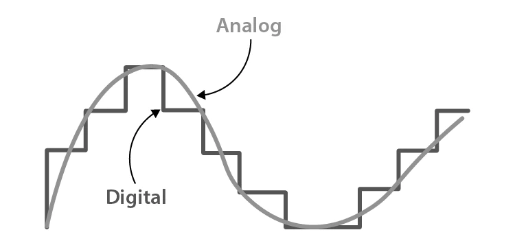
Comparison of Analog and Digital Communication Systems
Example Problem
A communication system transmits a signal that switches between two voltage levels representing binary digits. If the signal changes state 1000 times per second, what is the bit rate of this digital communication?
Solution:
The bit rate is the number of bits transmitted per second. Since each state change represents one bit, the bit rate is:
\[ \text{Bit rate} = 1000 \text{ bits per second} \]
Therefore, the system transmits data at 1000 bps.
Communication Channels: Wired and Wireless Mediums
Communication channels serve as the pathways through which signals travel from sender to receiver. These channels are primarily divided into wired and wireless categories.
Wired communication includes methods such as parallel wires, twisted pair cables, coaxial cables, and optical fibers. Each type offers different advantages in terms of bandwidth, noise immunity, and distance.
Wireless communication, on the other hand, transmits signals through the air or space using electromagnetic waves. This category encompasses ground wave, skywave, space wave, and satellite communications, enabling long-distance and mobile connectivity.
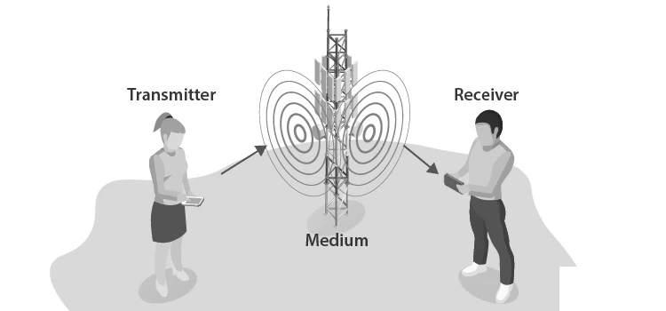
Various Communication Channels: Wired and Wireless
Example Problem
Identify which communication channel would be most suitable for transmitting high-speed internet over a long distance with minimal signal loss.
Solution:
Parallel and twisted pair wires are prone to interference and limited in bandwidth.
Coaxial cables offer better shielding but have distance limitations.
Optical fiber cables provide high bandwidth, low attenuation, and are ideal for long-distance, high-speed data transmission.
Hence, optical fiber communication is the best choice for this scenario.
Core Components of Communication Systems
Understanding the Role of Information and Signals
At the heart of any communication system lies the information or message, which can be audio, video, temperature readings, images, or other data forms. This information is transformed into signals—functions of time that carry the message in an electrical form suitable for transmission.
Transducers: Converting Physical Inputs to Electrical Signals
Transducers are devices that convert one form of energy into another. In communication, electrical transducers transform physical phenomena like sound or light into electrical signals. For instance, microphones convert sound waves into electrical signals, while photodetectors convert light into electrical signals.
Example Problem
A microphone converts sound waves into electrical signals. If the input sound frequency is 1 kHz, what is the frequency of the electrical signal produced?
Solution:
The electrical signal produced by the microphone has the same frequency as the input sound wave.
\[ \text{Frequency of electrical signal} = 1 \text{ kHz} \]
Thus, the output electrical signal frequency is 1 kHz.
Amplifiers: Enhancing Signal Strength
Signals often weaken during transmission. Amplifiers are electronic circuits that boost the amplitude of these signals to maintain their integrity over long distances. They can be placed anywhere between the transmitter and receiver and require a DC power source to operate.
Modulation Techniques: Preparing Signals for Transmission
Message signals typically have low frequency and amplitude, making them unsuitable for long-distance transmission. Modulation involves superimposing these signals onto high-frequency carrier waves to facilitate effective transmission. The resulting modulated wave carries the information over the channel.
Common modulation types include:
Amplitude Modulation (AM): The amplitude of the carrier wave varies in accordance with the message signal, while frequency remains constant.
Frequency Modulation (FM): The carrier wave's frequency changes based on the message signal, offering better noise resistance.
Phase Modulation (PM): The phase of the carrier wave shifts according to the message signal, providing enhanced immunity to noise.
Example Problem
A carrier wave of frequency 1 MHz is amplitude modulated by a message signal of frequency 5 kHz. What is the frequency of the modulated wave?
Solution:
The modulated wave contains the carrier frequency and sidebands at frequencies:
\[ f_c \pm f_m = 1\,\text{MHz} \pm 5\,\text{kHz} \]
Thus, the modulated wave frequencies are 995 kHz and 1.005 MHz along with the carrier at 1 MHz.
Transmitters and Antennas: Sending Signals into the Channel
The transmitter processes the modulated signal into a form suitable for sending through the communication channel. Antennas, typically metallic structures or wire arrays, radiate electromagnetic waves into space and also receive incoming waves. Their orientation affects the polarization of the transmitted or received waves.
Communication Channels and Their Challenges
The channel is the medium—such as cables or air—through which signals travel. However, channels introduce impairments like noise, attenuation, and distortion that degrade signal quality.
Noise: Unwanted Disturbances in Signal Transmission
Noise refers to any unwanted alteration in the signal during transmission. It arises from external sources like electromagnetic interference, lightning, or cosmic radiation, and internal sources such as thermal agitation of electrons within conductors.
Mitigation strategies include:
Designing cables with shielding to reduce external interference.
Employing digital transmission techniques to minimize noise effects.
Using filters like Band Pass Filters (BPF) or Low Pass Filters (LPF) at the receiver.
Attenuation: Signal Power Loss Over Distance
As signals travel through a medium, their power diminishes proportionally to the distance covered. Amplifiers are used to restore signal strength, and digital signals generally suffer less attenuation compared to analog signals.
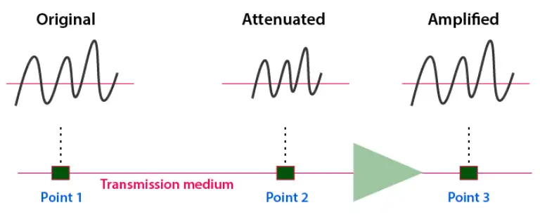
Signal Attenuation Over Transmission Medium
Distortion: Alteration of Signal Shape
Distortion occurs when the received signal's frequency or bandwidth differs from the original transmitted signal. This can be linear or nonlinear and affects the clarity of the received information.
Receivers and Demodulators: Extracting the Original Message
The receiver's role is to recover the original message from the transmitted signal. Demodulators perform the inverse of modulation, separating the message signal from the carrier wave to retrieve the information.
Repeaters: Extending Communication Range
Repeaters are devices placed along the transmission path that receive weakened signals, amplify them, and retransmit without distortion, thereby extending the effective communication distance.
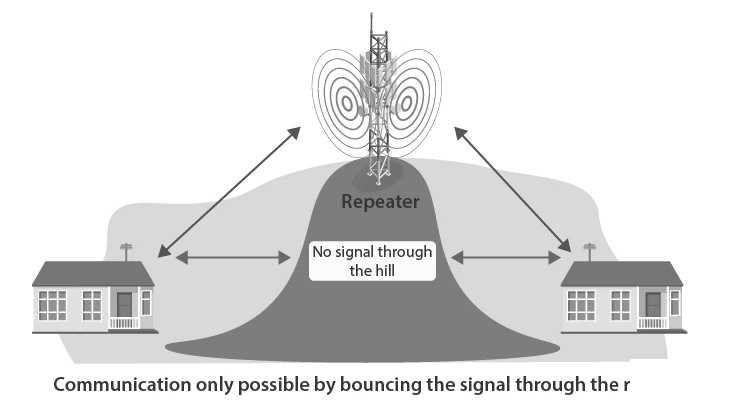
Functioning of a Repeater in Signal Transmission
Example Problem
A communication link has a total length of 100 km. If the signal attenuates by 0.5 dB per km, and a repeater is placed every 20 km, what is the total attenuation between repeaters?
Solution:
Attenuation per segment:
\[ 0.5 \text{ dB/km} \times 20 \text{ km} = 10 \text{ dB} \]
Each repeater amplifies the signal to compensate for this 10 dB loss before retransmission.
Overview of Communication System Architecture
Signal Flow from Source to Destination
The communication process begins with the information source, which generates the message. This message is converted into an electrical signal by the input transducer. The transmitter then modulates and prepares the signal for transmission through the channel. At the receiving end, the receiver demodulates and processes the signal, converting it back to a form understandable by the output transducer.
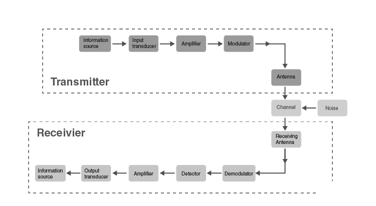
Block Diagram Illustrating Communication System Components
Example Problem
Identify the component responsible for converting physical signals like sound into electrical signals in a communication system block diagram.
Solution:
The input transducer performs this conversion.
For example, a microphone converts sound waves into electrical signals.
Quick Reference: Key Terms and Concepts
Term | Definition |
|---|---|
Information | Data or message to be transmitted, such as audio, video, or sensor readings. |
Signal | Electrical representation of information varying over time. |
Transducer | Device converting one form of energy to another, e.g., microphone. |
Amplifier | Electronic circuit that increases signal strength. |
Modulation | Process of superimposing message signal on a carrier wave. |
Demodulation | Extraction of the original message from the modulated carrier. |
Transmitter | Device that prepares and sends the signal through the channel. |
Receiver | Device that recovers the message from the received signal. |
Channel | Medium through which the signal travels, e.g., cable or air. |
Noise | Unwanted disturbances affecting signal quality. |
Glossary of Essential Terms
Term | Meaning |
|---|---|
Amplitude Modulation (AM) | Modulation technique varying the amplitude of the carrier wave. |
Frequency Modulation (FM) | Modulation method changing the frequency of the carrier wave. |
Phase Modulation (PM) | Modulation where the phase of the carrier wave is altered. |
Attenuation | Reduction in signal strength over distance. |
Distortion | Change in signal waveform causing alteration of information. |
Repeater | Device that amplifies and retransmits signals to extend range. |
Transmitter | Equipment that sends the modulated signal into the channel. |
Receiver | Equipment that captures and processes the transmitted signal. |
Transducer | Device converting physical signals to electrical signals and vice versa. |
Channel | Physical medium for signal transmission. |
Frequently Asked Questions
What are the fundamental parts of a communication system?
The essential components include the information source, input transducer, transmitter, communication channel, receiver, and output transducer.
Which modulation methods are commonly used in communication?
Amplitude Modulation (AM), Frequency Modulation (FM), and Phase Modulation (PM) are the primary techniques.
How are communication systems classified?
They are classified based on technology into analog and digital systems, and based on the channel into wired and wireless systems.
What causes noise in communication channels?
Noise arises from external sources like electromagnetic interference and internal sources such as thermal agitation of electrons.
How does a repeater improve communication?
Repeaters amplify weakened signals and retransmit them, extending the communication distance without distortion.