Understanding Circuit Diagrams: Symbols and Examples
Fundamentals of Circuit Diagrams
What Defines a Circuit Diagram?
A circuit diagram, often called an electrical schematic, is a simplified graphical illustration of an electrical circuit. It uses standardized symbols to represent various electrical components and their interconnections, enabling engineers and technicians to visualize the circuit layout clearly. This abstraction helps in designing, troubleshooting, and maintaining electrical systems efficiently.
Interpreting Circuit Diagrams
To grasp how circuit diagrams function, consider a basic example featuring a power source, a voltmeter, an ammeter, and a resistor. Each component is depicted by a unique symbol, and their connections illustrate the flow of current and voltage within the circuit.

Example Problem
Identify the components shown in a circuit diagram that includes a voltage source, an ammeter, a voltmeter, and a resistor connected in series. Explain the role of each symbol.
Solution:
- Voltage Source: Provides electrical energy to the circuit.
- Ammeter: Measures the current flowing through the circuit.
- Voltmeter: Measures the potential difference across the resistor.
- Resistor: Limits the current flow within the circuit.
Understanding these symbols helps in analyzing the circuit's behavior and functionality.
Common Symbols Used in Circuit Diagrams
Representation of Power Sources
Electric cells and batteries are fundamental power sources in circuits. An electric cell is depicted by a pair of parallel lines of unequal length; the longer line indicates the positive terminal, while the shorter line marks the negative terminal. A battery symbol consists of multiple such cells connected in series, showing the combined voltage supply.


Example Problem
Draw the symbol for a battery made up of four electric cells connected in series and explain the significance of the terminals.
Solution:
The battery symbol consists of four pairs of parallel lines arranged sequentially. Each pair represents a cell, with the longer line as the positive terminal and the shorter as the negative. The positive terminal of one cell connects to the negative terminal of the next, combining their voltages to supply higher power.
Switches and Wire Connections
Switches control the flow of current by opening or closing the circuit. They are shown as a break in a line, which closes when the switch is on, allowing current to pass. Wire joints are marked by a dot where wires connect electrically, while crossing wires without a dot indicate no electrical connection.



Example Problem
Explain how to distinguish between connected and unconnected wires in a circuit diagram and describe the function of a switch symbol.
Solution:
- Connected wires are shown intersecting with a dot at the junction, indicating electrical contact.
- Wires crossing without a dot are not connected and simply pass over each other.
- A switch symbol shows a break in the line; when closed, it completes the circuit allowing current flow, and when open, it interrupts the current.
Symbols for Electrical Components
Various components like bulbs, resistors, capacitors, and meters have distinct symbols. An electric bulb is shown as a circle with a cross inside, representing the filament. Resistors appear as zigzag lines, while variable resistors include an arrow indicating adjustable resistance. Inductors are depicted as coils, and capacitors as parallel lines, with polarized capacitors having a curved line to show polarity. Measuring instruments like ammeters and voltmeters are circles with 'A' and 'V' letters respectively.








Example Problem
Describe the symbols for a variable resistor and a polarized capacitor and explain their significance in a circuit.
Solution:
- The variable resistor symbol includes a zigzag line with an arrow crossing it, indicating that its resistance can be adjusted to control current flow.
- The polarized capacitor symbol has one straight and one curved line, showing the positive and negative terminals, which is crucial for correct orientation in the circuit.
Practical Circuit Diagram Illustrations
Example of Series Connection with Batteries and Bulbs
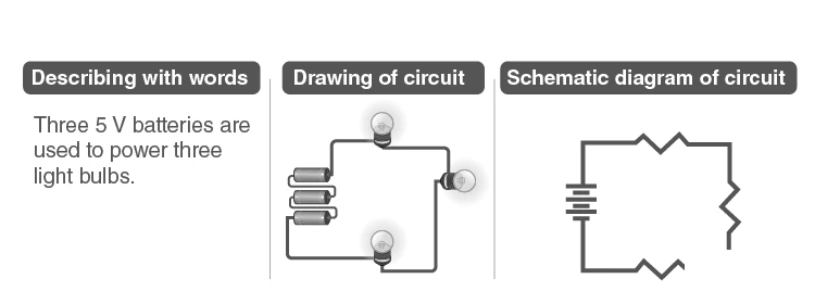
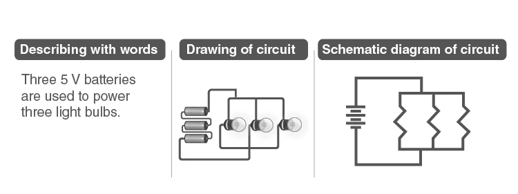
Consider a circuit powered by three 4.5 V batteries connected in series to light up three bulbs. The bulbs are arranged so that the current flows sequentially through each one, demonstrating a series connection. This setup ensures the same current passes through all bulbs, but the voltage divides among them.
Example Problem
In a circuit with three bulbs connected in series to a 13.5 V battery, calculate the voltage across each bulb if all bulbs have equal resistance.
Solution:
Since the bulbs are in series, the voltage divides equally:
\[ V_{\text{total}} = 13.5 \text{ V}, \quad V_{\text{each}} = \frac{13.5 \text{ V}}{3} = 4.5 \text{ V} \]
Each bulb experiences 4.5 V across it.
Exam Tip: Remember, in series circuits, current remains constant through all components, while voltage divides. In parallel circuits, voltage remains the same across components, but current divides.
Summary Table for Quick Review
| Component | Symbol Description | Function |
|---|---|---|
| Electric Cell | Pair of parallel lines (longer positive) | Supplies electrical energy |
| Battery | Multiple cells in series | Provides higher voltage |
| Switch | Line with gap (open/closed) | Controls current flow |
| Wire Joint | Dot at wire intersection | Indicates electrical connection |
| Crossing Wires | Wires crossing without dot | No electrical connection |
| Electric Bulb | Circle with cross inside | Converts electrical energy to light |
| Resistor | Zigzag line | Limits current flow |
| Variable Resistor | Zigzag with arrow | Adjustable resistance |
| Inductor | Coil loops | Stores energy magnetically |
| Fixed Capacitor | Two parallel lines | Stores electrical charge |
| Polarized Capacitor | Parallel lines with curved line | Stores charge with polarity |
| Ammeter | Circle with "A" | Measures current |
| Voltmeter | Circle with "V" | Measures voltage |
Glossary of Key Terms
| Term | Definition |
|---|---|
| Circuit Diagram | A graphical representation of an electrical circuit using symbols. |
| Electric Cell | A device that converts chemical energy into electrical energy. |
| Battery | Multiple electric cells connected to provide higher voltage. |
| Switch | A device that opens or closes a circuit to control current flow. |
| Resistor | A component that resists the flow of electric current. |
| Variable Resistor | A resistor whose resistance can be adjusted. |
| Inductor | A coil that stores energy in a magnetic field. |
| Capacitor | A device that stores electrical energy in an electric field. |
| Ammeter | An instrument used to measure electric current. |
| Voltmeter | An instrument used to measure voltage or potential difference. |
Frequently Asked Questions
What is the main purpose of a circuit diagram?
A circuit diagram visually represents electrical components and their connections, simplifying the design and troubleshooting of circuits.
How can you tell if wires are connected in a circuit diagram?
Wires connected electrically are shown with a dot at their intersection; if no dot is present, the wires simply cross without connection.
What symbol represents a resistor in a circuit diagram?
A resistor is depicted by a zigzag line, indicating its role in limiting current flow.
How does a variable resistor differ from a fixed resistor symbolically?
A variable resistor includes an arrow across the zigzag line, showing that its resistance can be adjusted.
Why is polarity important for polarized capacitors?
Polarized capacitors must be connected correctly according to their positive and negative terminals to function properly and avoid damage.