CLASS 12-PCB . PHYSICS . PHYSICS PART I . MOVING CHARGES-AND-MAGNETISM
Chapter 4 : Moving Charges And Magnetism
Ch 4
PHYSICS
CLASS 12-PCB
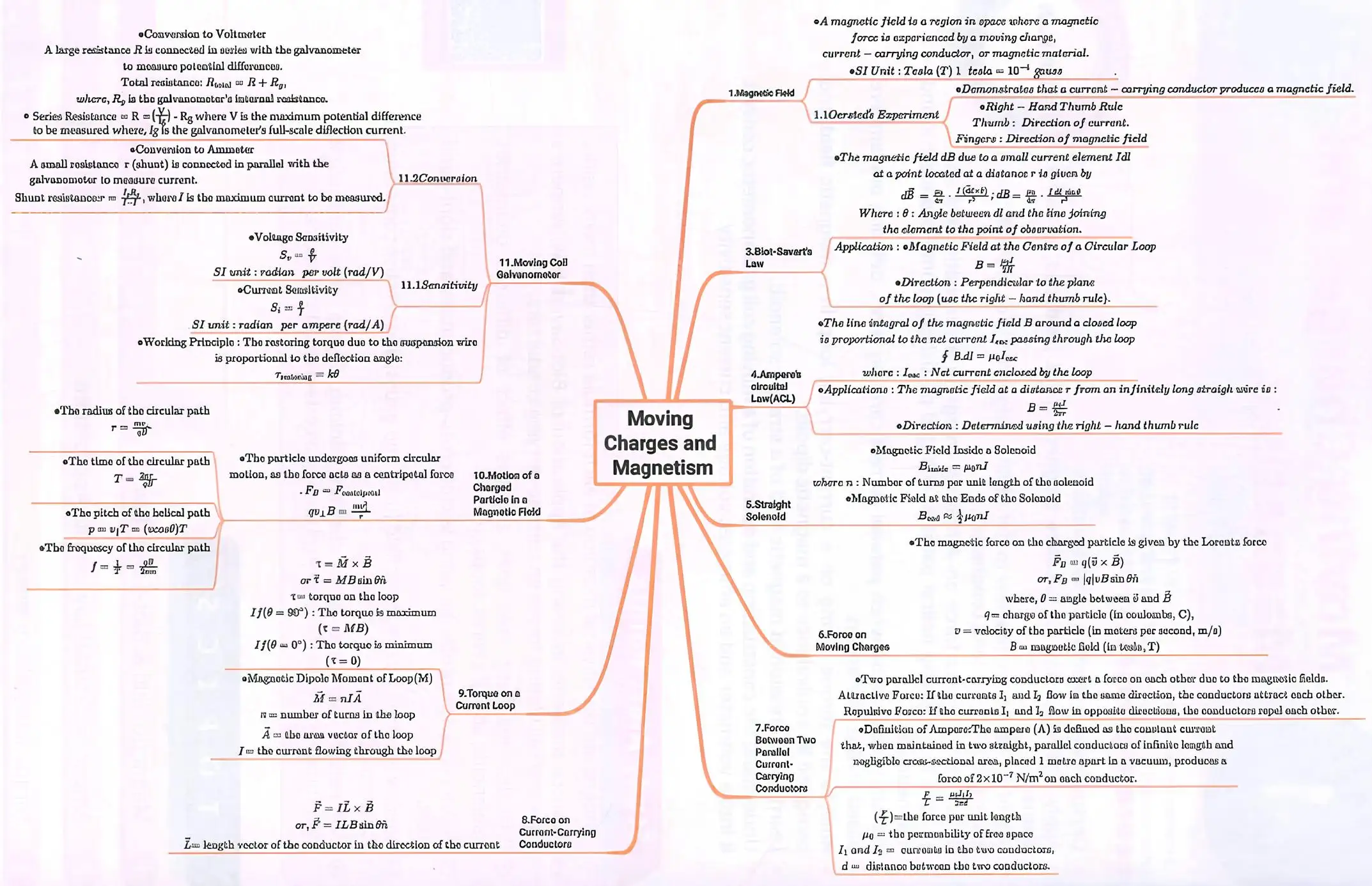
Magnetic Field and Biot-Savart Law
Concept of Magnetic Field
Magnetic field is a region around a magnet where force of magnetism acts which affects other magnets and magnetic materials.
Magnetic field also known as B-field can be pictorially represented by magnetic field lines.
Magnetic field lines: Magnetic field lines also known as magnetic flux lines, are imaginary lines those represent the direction and strength of a force.
Magnetic fields are produced by electric currents, which can be macroscopic currents in wires, or microscopic currents associated with electrons in atomic orbits.
Lorentz Force: When a charge q moving with velocity v enters a region where both magnetic field and electric field exist, both fields exert a force on it.
Lorentz Force, 𝐅⃗ = q(𝐄⃗ +𝐯⃗ × 𝐁⃗)
where, 𝐅⃗ = magnetic force, q = charge, 𝐯⃗ = velocity of the charged particle, 𝐁⃗ = magnetic field, 𝐄⃗ = electric field, q𝐄⃗ = electric force on the charge, q(𝐯⃗ × 𝐁⃗) = magnetic force on the charge
SI unit of magnetic field is tesla.
1 tesla = 10₄ gauss
When a test charge q, enters a magnetic field 𝐁⃗ directed along negative z-axis with a velocity 𝐯⃗ making an angle 0 with the z-axis, then,
𝐅⃗ₘ = q₀(𝐯⃗ × 𝐁⃗) = q₀vB sinθ n̂
Oersted's experiment
Oersted observed that:
When there is no current, compass needle below a wire shows no deflection.
When current flows through a wire in a definite direction, then the compass needle placed close to it deflects in a particular direction.
When the flow of current is reversed, deflection in the compass needle occurs in the opposite direction.
From the experiment, it is concluded that an electric current produces a magnetic field which surrounds the wire.
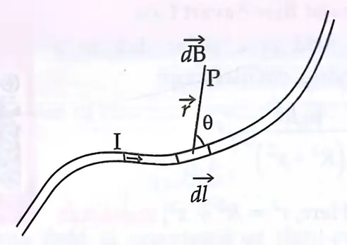
Biot-Savart Law: The magnetic field due to a current element at a nearby point is given by:
The magnetic field \( dB \) created by a small segment of current-carrying wire is calculated using the Biot-Savart law.
Here, a current element \( I \) flows through a small wire segment \( dl \), and the magnetic field at point P is calculated considering the distance \( r \) and angle \( \theta \) between \( dl \) and \( r \).
𝐝⃗𝐥⃗ = Vector length of a small section of wire in the direction of current
𝐫⃗= Positional vector from a section of wire to the point where the magnetic field is measured
I= Current in the wire
θ =Angle between𝐝⃗𝐥⃗ and 𝐫⃗
μ₀ = Permeability of free space and μ₀ = 4π × 10⁻⁷ Wb/Am
The magnitude of magnetic field,
This formula shows the magnitude of magnetic field \( dB \) created by a small current element, depending on current, length, angle, and distance.
which is known as Biot-Savart / law.
Permeability: It is also called magnetic permeability, is a constant of proportionality that exists between magnetic induction and magnetic field intensity.
Example: Calculate magnetic field at point on y-axis due to a small current element on x-axis using Biot-Savart law.
Given: Current I = 10 A, length dl = 1 cm, distance r = 0.5 m, angle θ = 90°.
Using Biot-Savart law:
\[ |dB| = \frac{\mu_0}{4\pi} \frac{Idl \sin \theta}{r^2} = 10^{-7} \times \frac{10 \times 10^{-2} \times 1}{(0.5)^2} = 4 \times 10^{-8} \text{ T} \]
Direction of magnetic field is along +z-axis by right-hand rule.
Application of Biot-Savart Law
Magnetic field at a point due to a current carrying circular loop:
𝐁⃗ = μ₀ I R² / [ 2 ( R² + x² )³ᐟ² ] r̂
[ Here, r² = R² + x² ]
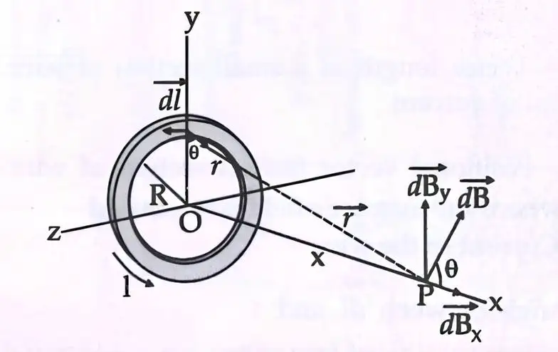
Current loop of radius R carrying current I produces magnetic field at point P on axis.
Magnetic field at the centre of a coil of N turns:
𝐁⃗ = ( μ₀NI/2R ) r̂ (x = 0)
Magnetic field at a very large distance from the centre:
B = 2μ₀NIA/4πx³ (Here, R² << r² or, R² + x² ≈ x²)
where, A = Area of circular loop = πR²
Magnetic field due to current carrying circular arc with centre O is:
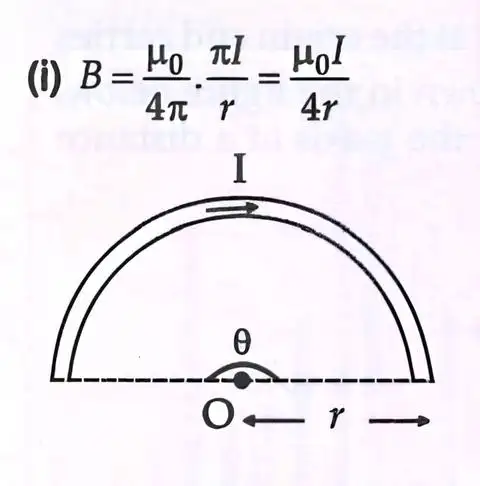
Magnetic field at center of semicircular wire carrying current I is given by B = μ₀I/4r.
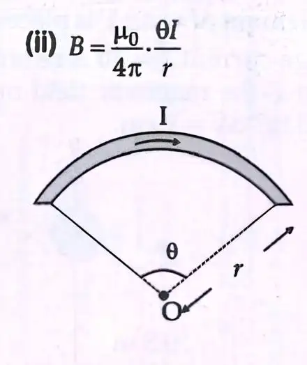
Magnetic field at center of circular arc carrying current I subtending angle θ is B = (μ₀ θ I)/(4 π r).
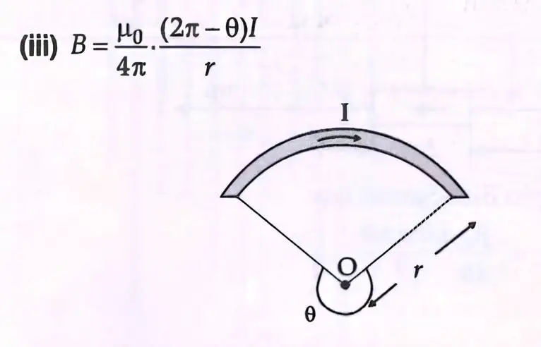
Magnetic field at center due to current carrying arc of angle (2π - θ) is B = (μ₀ (2π - θ) I)/(4 π r).
Magnetic field at common centre of non-coplanar and concentric coils, where both coils are perpendicular to each other will be:
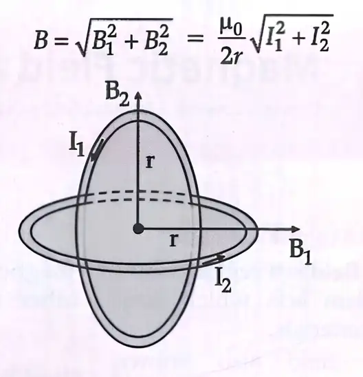
Total magnetic field B = (μ₀/2r) √(I₁² + I₂²) for two perpendicular coils carrying currents I₁ and I₂.
Example 2:
A straight wire carrying a current of 12 A is bent into a semi-circular arc of radius 2.0 cm as shown in the figure(a). Consider the magnetic field B at the centre of the arc.
(a) What is the magnetic field due to the straight segments?
(b) In what way the contribution to B from the semicircle differs from that of a circular loop and in what way does it resemble?
(c) Would your answer be different if the wire were bent into a semi-circular arc of the same radius but in the opposite way as shown in figure(b)?
Fig. a shows current flowing clockwise; Fig. b shows current flowing counterclockwise.
Sol.
(a) 𝐝⃗𝐥⃗ and 𝐫⃗ for each element of the straight segments are parallel. Therefore, 𝐝⃗𝐥⃗ × 𝐫⃗ =0. Straight segments do not contribute to |B|.
(b) For all segments of the semicircular arc, 𝐝⃗𝐥⃗ × 𝐫⃗ are all parallel to each other (into the plane of the paper). This is the resemblance of the two fields. So, they add up in magnitude. Hence, direction of B for a semicircular arc is given by the right-hand rule and the magnitude is half that of a circular loop. This is the difference of two fields.
Magnitude of magnetic field due to the semicircle
= B = μ₀I/4r
= 4π×10⁻⁷×12/4×2×10⁻²
= 1.9×10⁻⁴T
Thus B is1.9×10⁻⁴T normal to the plane of the paper going into it.
(c) Same magnitude of B but opposite in direction to (b).
Example 3:
Consider a tightly wound 100 turn coil of radius 10 cm, carrying a current of 1 A. What is the magnitude of the magnetic field at the centre of the coil?
Sol.
Since the coil is tightly wound, then radius R = 10 cm = 0.1 m
The number of turns N= 100
The magnitude of the magnetic field is,
B = μ₀NI/2R = 4π×10⁻⁷×10²×1/2×10⁻¹
= 2π×10⁻⁴ = 6.28 ×10⁻⁴ T
Practice Set
- Level 1: What is the SI unit of magnetic field? Explain the physical meaning of magnetic field lines.
- Level 2: Using Biot-Savart law, explain why the magnetic field at the center of a circular loop is proportional to the current and inversely proportional to the radius.
- Level 3: A current element of length 2 cm carries 5 A current. Calculate the magnetic field at a point 10 cm away perpendicular to the element. Use Biot-Savart law.
Answer Key
- Level 1: The SI unit of magnetic field is tesla (T). Magnetic field lines represent the direction and strength of magnetic force; they emerge from the north pole and enter the south pole of a magnet.
- Level 2: According to Biot-Savart law, magnetic field \( B \propto I \) because the magnetic field strength increases with current. It is inversely proportional to the square of the distance \( r^2 \), so at the center of the loop, \( B \propto 1/R \) where \( R \) is the radius.
- Level 3: Given \( I=5 \text{ A}, dl=2 \text{ cm}=0.02 \text{ m}, r=0.1 \text{ m}, \theta=90^\circ \)
\[ B = \frac{\mu_0}{4\pi} \frac{I dl \sin \theta}{r^2} = 10^{-7} \times \frac{5 \times 0.02 \times 1}{(0.1)^2} = 1 \times 10^{-7} \text{ T} \]
Ampere's Circuital Law
Statement and Explanation
Ampere’s circuital law states that the line integral of magnetic field around a closed path is μ₀ times the total current enclosed by the path:
∮B.dI = μ₀I
where,
B = Magnetic field
dI = Infinitesimal segment of the path
Infinitesimal segment: An infinitesimal segment is a part of the line or wire that is smaller than any feasible measurement, but not zero in size.
μ₀ = Magnetic permeability of free space
I = Enclosed electric current by the path
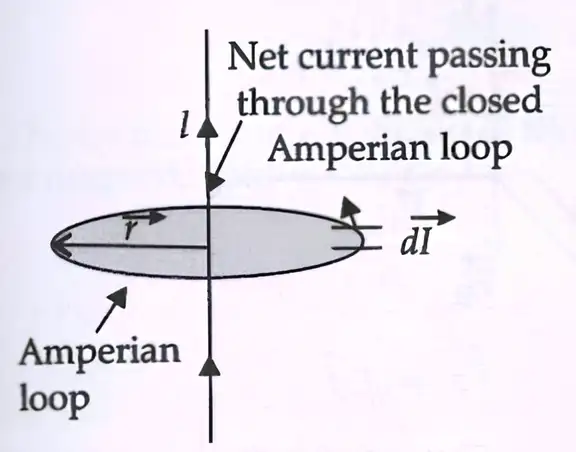
An Amperian loop is an imaginary closed path drawn around a conductor carrying current I.
Magnetic field at a point does not depend on the shape of Amperian loop and remains same at every point on the loop.
Force on a current carrying conductor
For a steady current I in the conducting wire, in the presence of an external magnetic field B, the force on the charge carriers is:
F = (nlA)qvd × B
where q is the value of the charge on a carrier, n is the number density of charge carriers, l is the length of the conductor, A is the area of cross section of the conductor and vd is the drift velocity of the charge carriers.
Now, nqvd is the current density J and ┃(nqvd)┃ A is the current I.
Thus, F = [(nqvd)lA] × B = [JAl] × B = Il× B
Current Density: It is a measure of the amount of electric current flowing per unit area of a cross-section. It describes how concentrated the electric current is within a conductor. Current density is a vector quantity, meaning it has both a magnitude and direction.
Forces between two parallel currents
Two parallel wires separated by a distance r having currents I₁ and I₂ where magnetic field strength at the second wire due to current flowing in the first wire is given as:
B = μ₀I₁/2πr
In this, the field is orientated at right-angle to the second wire where force per unit length on the second wire is:
F/l = μ₀I₁I₂/2πr
Magnetic field strength at first wire due to the current flowing in the second wire is:
B = μ₀I₂/2πr
One ampere is the magnitude of current which, when flowing in each parallel wire one metre apart, results in a force between the wires as 2 X 10⁻⁷N per metre of length.
Applications of Ampere’s law to infinitely long straight wire, straight solenoids
(i) Magnetic Field due to long straight wire Ampere's law describes the magnitude of magnetic field of a straight wire as:
B = μ₀I/2πr
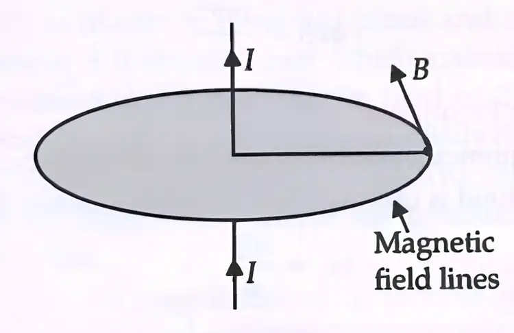
Field B is tangential to a circle of radius centred on the wire.
Magnetic field B and path length remain parallel every where.
(ii) Magnetic Field due to Solenoid:
Solenoid:
A solenoid is a tightly wound helical coil of insulated wire whose diameter is small compared to its length. Magnetic field generated at the centre or at the core of a current carrying solenoid is uniform and is directed along the axis of the solenoid.
Magnetic field due to a straight solenoid:
at any point in the solenoid, B = μ₀nI
at the ends of the solenoid, Bₑₙᵈ = μ₀nI/2
where, n = number of turns per unit length, I = current in the coil.
Example 4:A solenoid of length 0.5 m has a radius of 1 cm and is made up of 500 turns. It carries a current of 5A. What is the magnitude of the magnetic field inside the solenoid?
Sol. The number of turns per unit length is,
n = 500/0.5 = 1000 turns/m
Here, the length l = 0.5 m and radius r = 0.01 m.
Thus, l/r = 50 i.e., l>>r.
Hence, B = μ₀nI
= 4π×10⁻⁷×10³×5
= 6.28×10⁻³T
Motion of a Charged particle in a Uniform Magnetic Field
Centripetal Force in a Magnetic Field:
For a charged particle moving in a magnetic field in a circular path, the centripetal force is provided by the magnetic force.
Fc = mv²/r
Centripetal Force and Magnetic Force Equality:
Equating the centripetal force to the magnetic force, we get:
qvB = mv²/r
Centripetal Force: The force that is necessary to keep an object moving in a curved path and that is directed along the radius and towards the centre of rotation.
Angular Frequency:
The frequency of revolution of the charged particle in a magnetic field is called the cyclotron frequency (ωc).
ωc = qB/m
Radius of the Circular Path:
The radius of the circular path is given by:
r = mv/qB
Angular Frequency and Period of Revolution:
The angular frequency (ω) and the period of revolution (T) are related to the angular frequency:
T = 2π/ωc
Helical Motion in a Uniform Magnetic Field:
If a charged particle has an initial velocity component parallel to the magnetic field, it undergoes helical motion in addition to circular motion.
Helical Motion: It is the motion generated when one component of the velocity is constant in amplitude and direction which is straight-line motion and the other component is constant in speed but changes in direction evenly (circulation motion).
Motion of a Charged particle in combined Electric and Magnetic Fields:
When a charge q is moving with a velocity v in presence of both electric and magnetic fields experiences a force given by
𝐅⃗ = q(𝐄⃗+𝐯⃗+ 𝐁⃗) = 𝐅⃗E+ 𝐅⃗B
But when electric and magnetic fields are perpendicular to each other and also perpendicular to the velocity of the particle, then,
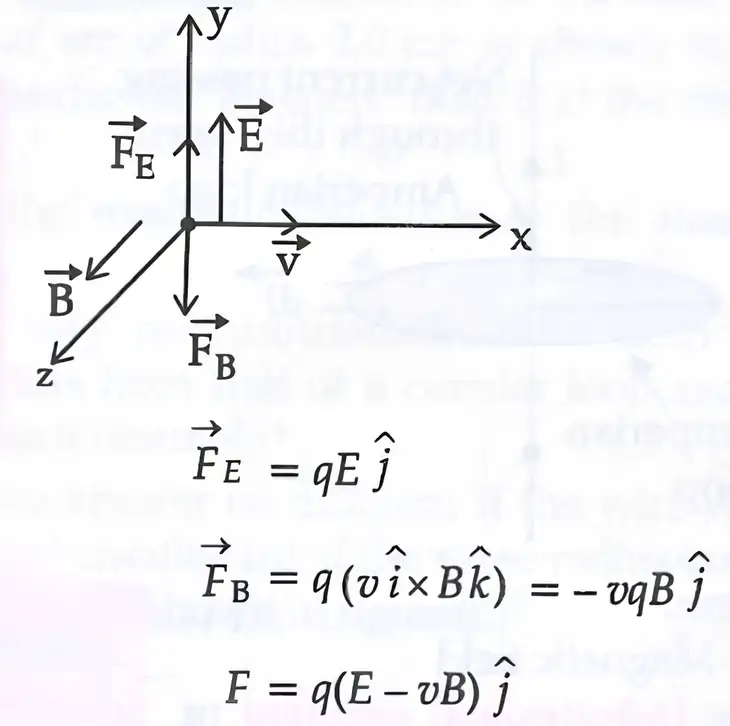
Electric and magnetic forces are in opposite directions. If E and B are adjusted such that magnitudes of forces are equal, total force is zero and charge moves undeflected.
Condition: v = E/B (Velocity Selector)
MNEMONICS
Concept: Path of a charged particle in a uniform magnetic field depending on the angle between the magnetic field and the velocity of the particle:
Mnemonics: Circle -circle ninety (90°) angle,
go straight if it zero (0°),
Go for helical, all other angle
magnet field is hero.
Interpretations:
Circle -circle ninety (90°) angle ⇒ Path is a circle if angle between magnetic field and velocity of charged particles is 90°.
Go straight if it zero (0°) ⇒ Path is a straight line if angle between magnetic field and velocity of charged particles is 0°.
Go for helical, all other angle ⇒ Path is a helix for any other angle between magnetic field and velocity of charged particle.
Key Formulae
Ampere's circuital law:
Magnetic field due to a long straight wire: B = μ₀I/2πr
Magnetic field inside a solenoid: B = μ₀nI
Magnetic field at the ends of solenoid: Bₑₙᵈ = μ₀nI/2
Force between two parallel wires, F = μ₀/4π × 2I₁I₂/a × l
Force between two moving charged particles, Fₘ = μ₀/4π × q₁q₂v₁v₂/a × r²
The frequency of revolution of the charged particle in a magnetic field ωc = qB/m
Radius of the circular path: r = mv/qB
The period of revolution (T): T = 2π/ωc
Practice Set
- Level 1: State Ampere's circuital law and explain the magnetic field inside a solenoid.
- Level 2: Derive the expression for the magnetic field due to a long straight current-carrying wire using Ampere's law.
- Level 3: A proton moves in a magnetic field of 0.5 T with a velocity perpendicular to the field. Calculate the radius of its circular path if its speed is \( 2 \times 10^6 \) m/s. (Mass of proton = \( 1.67 \times 10^{-27} \) kg, charge = \( 1.6 \times 10^{-19} \) C)
Answer Key
- Level 1: Ampere's circuital law states that the line integral of magnetic field around a closed path equals \( \mu_0 \) times the current enclosed. Inside a solenoid, the magnetic field is uniform and given by \( B = \mu_0 n I \).
- Level 2: Using Ampere's law on a circular path around the wire, \( \oint B dl = B (2\pi r) = \mu_0 I \), so \( B = \frac{\mu_0 I}{2\pi r} \).
- Level 3: Radius \( r = \frac{mv}{qB} = \frac{1.67 \times 10^{-27} \times 2 \times 10^6}{1.6 \times 10^{-19} \times 0.5} = 4.18 \times 10^{-2} \text{ m} \).
Torque and Galvanometer
Torque on Current Loop
A rectangular loop of length l, breadth b with current I flowing through it is in a uniform magnetic field B where angle θ is between the normal and in the direction of the magnetic field, then the torque experienced is:
τ = nBIA sinθ
where, n = number of turns in the coil
∴ nIA = M
Further,
τ =MB sinθ
Torque is maximum when the coil is parallel to the magnetic field and is zero when the coil is perpendicular to the magnetic field
In vector notation, torque τ̅ experienced will be
τ̅ = 𝐌⃗×𝐁⃗
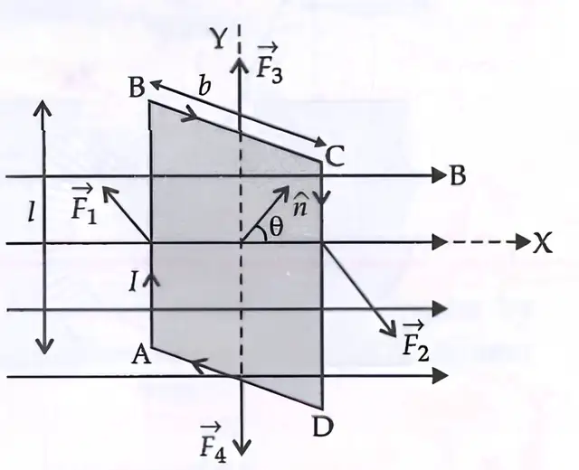
Rectangular loop ABCD carrying current I in magnetic field B experiences forces on sides, creating torque that tends to rotate the loop.
Physics problem involving circular coil carrying current in magnetic field; calculation of magnetic field, magnetic moment, torque, and angular speed.
Example 6(a) A current-carrying circular loop lies on a smooth horizontal plane. Can a uniform magnetic field be set up in such a manner that the loop turns around itself (i.e., turns about the vertical axis)?
(b) A current-carrying circular loop is located in a uniform external magnetic field. If the loop is free to turn, what is its orientation of stable equilibrium? Show that in this orientation, the flux of the total field (external field + field produced by the loop) is maximum.
(c) A loop of irregular shape carrying current is located in an external magnetic field. If the wire is flexible, why does it change to a circular shape?
Sol. (a) In the scenario of a horizontal circular loop carrying current, the torque (τ = IAB sin θ) acting on the loop is indeed in the plane of the loop. Therefore, the loop would not rotate about its vertical axis, as the torque is unable to produce rotation in that direction.
(b) In the orientation of stable equilibrium, the area vector A of the loop should indeed be aligned in the direction of the external magnetic field. In this configuration, the magnetic field produced by the loop and the external magnetic field are both normal to the plane of the loop and in the same direction. As a result, the torque on the loop is maximum, and the loop is in a stable equilibrium position.
(c) It assumes a circular shape with its plane normal to the field to maximise flux, since for a given perimeter, a circle encloses a greater area than any other shape.
Moving coil galvanometer
It is an instrument used for the detection and measurement of small electric currents.
When a current carrying coil is suspended in a uniform magnetic field, it experiences a torque which rotates the coil.
The force experienced by each side of the galvanometer is F = BIl which are opposite in direction.
Opposite and equal forces form the couple which generates deflecting torque on the coil having a number of turns n is given as:
τ = F×b = nBIl × b = nBIA
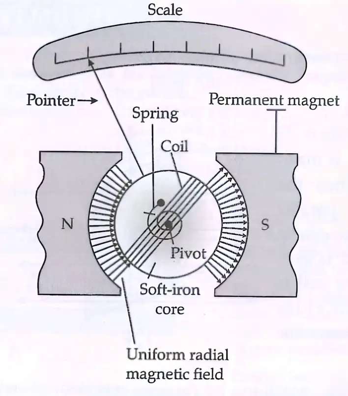
Structure of moving coil galvanometer: coil placed between poles of permanent magnet, current causes rotation, pointer shows current strength.
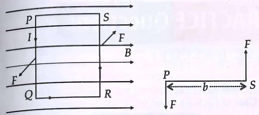
Rectangular loop in magnetic field experiences forces on sides creating torque that tends to rotate the loop.
In moving coil galvanometer, current in the coil is directly proportional to the angle of the deflection of the coil, I∞ θ i.e., where, θ is the angle of deflection.
Current sensitivity of galvanometer
Current sensitivity: The deflection produced per unit current.
Current Sensitivity, θ/I = nBA/C
Voltage sensitivity: The deflection per unit voltage.
Voltage sensitivity, θ/V = θ/IG = nBA/CG
where, G = galvanometer resistance, C = torsional constant.
Increase in sensitivity of moving coil galvanometer depends on:
- number of turns n
- magnetic field B
- area of coil A
- torsional constant
Conversion of galvanometer
A galvanometer can be converted into an ammeter by connecting a low resistance known as shunt in parallel with the galvanometer coil.
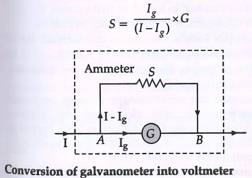
Conversion of galvanometer into voltmeter by connecting high resistance in series with galvanometer coil.
R = (V/Ig) - G
Ig = current for full-scale deflection of galvanometer.
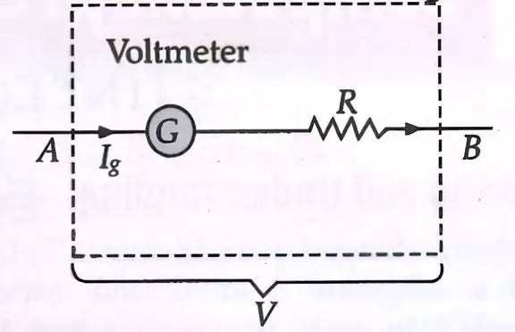
Internal structure of voltmeter: galvanometer and resistor in series to measure voltage.
Example 7:In the circuit given below, current is to be measured. What is the value of the current if the ammeter shown
(a) is a galvanometer with a resistance R_G = 60.00 Ω
(b) is a galvanometer described in (a) but converted to an ammeter by a shunt resistance = 0.02 Ω
(c) is an ideal ammeter with zero resistance?
Simple electrical circuit with battery, resistor, and ammeter connected in series.
Sol. (a) Total resistance in the circuit is, R_G + 3 = 63Ω
Hence, I = 3/63 = 0.048 A.
(b) Resistance of the galvanometer converted to an ammeter is,
R = (R_G r_s)/(R_G + r_s) = (60 × 0.02)/(60 + 0.02) = 0.02Ω
Total resistance in the circuit is, 0.02Ω + 3Ω = 3.02Ω
Hence, I = 3/3.02 = 0.99A.
(c) For the ideal ammeter with zero resistance,
I = 3/3 = 1.00A.
Key Formulae
τₘₐₓ = NBIA
Current Sensitivity = θ/I = nAB/C
Voltage Sensitivity = θ/V = nAB/CG