CLASS 12-PCB . PHYSICS . PHYSICS PART I . ALTERNATING CURRENT
Chapter 7 : Alternating Current
Ch 7
PHYSICS
CLASS 12-PCB
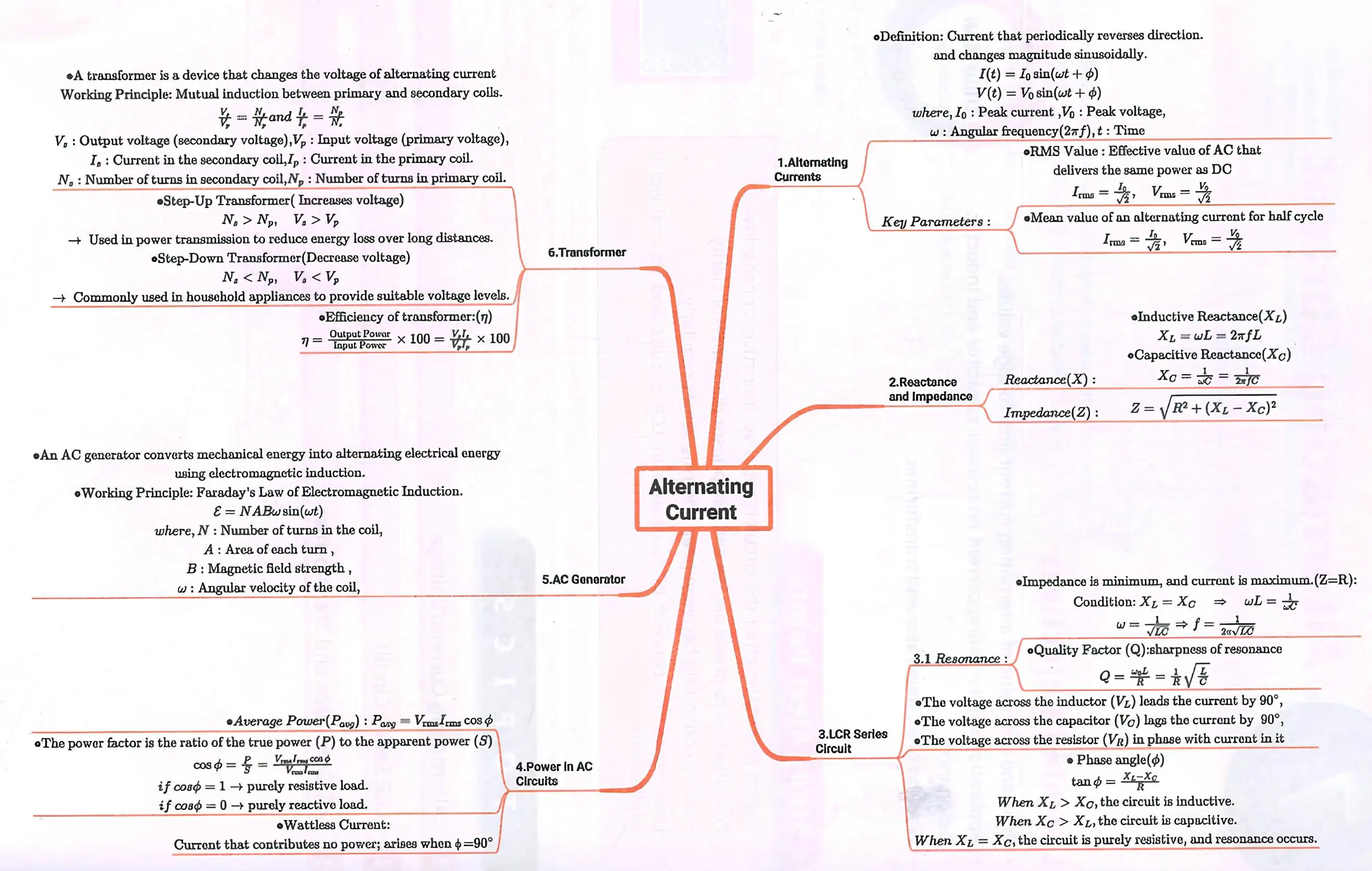
Alternating Current
Nature of Alternating Current
Alternating current (AC) is an electric current that reverses its direction periodically, unlike direct current (DC) which flows in one direction. The current varies sinusoidally with time and can be represented as \( I = I_0 \sin \omega t \) or \( I = I_0 \cos \omega t \), where \( I_0 \) is the peak current and \( \omega \) is the angular frequency.
The frequency \( f \) is the number of cycles per second, measured in Hertz (Hz). In India, the standard frequency of AC is 50 Hz. The time period \( T \) is the time taken to complete one cycle.
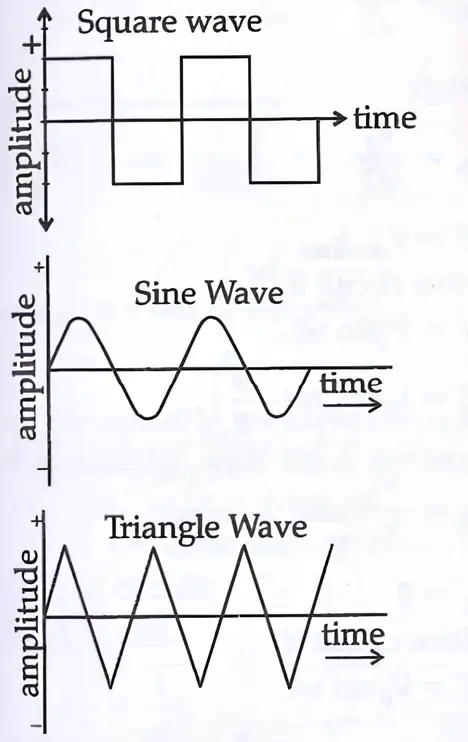
Waveforms of AC
AC waveforms include square wave, sine wave, and triangle wave. The sine wave is the most common, characterized by smooth periodic oscillations. Square waves change abruptly between high and low values, while triangle waves rise and fall linearly.
Peak and Root Mean Square Values
The root mean square (rms) value of AC current or voltage is the effective value that delivers the same power as a DC current of the same magnitude. It is given by:
\( I_{rms} = \frac{I_0}{\sqrt{2}} = 0.707 I_0 \)
\( V_{rms} = \frac{V_0}{\sqrt{2}} = 0.707 V_0 \)
AC in Pure Inductive and Capacitive Circuits
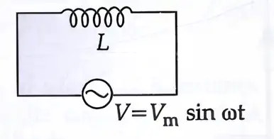
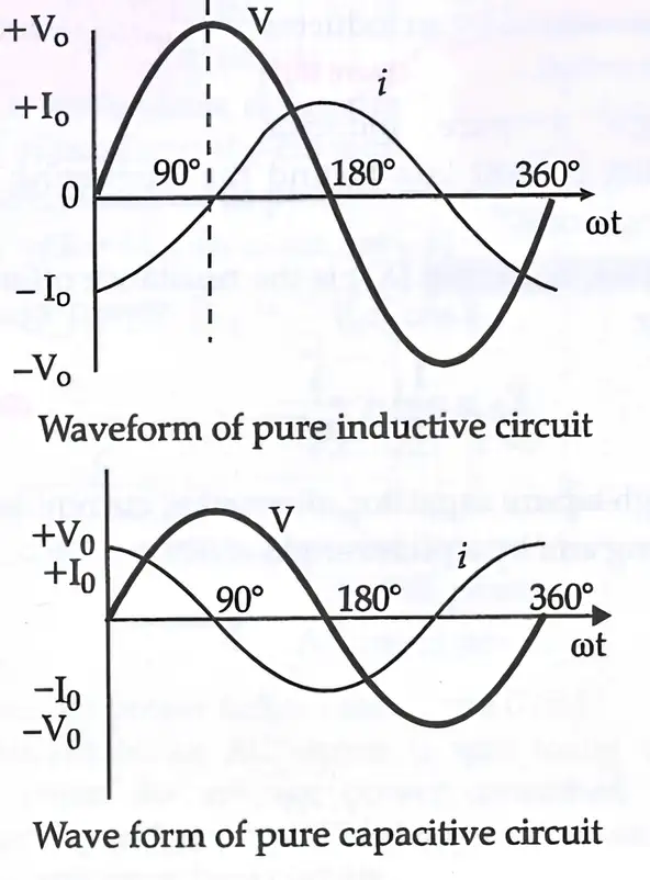
In a pure inductive circuit, the current lags the voltage by 90° (\( \pi/2 \) radians). The voltage and current are given by:
\( V = V_0 \sin \omega t \)
\( I = I_0 \sin (\omega t - \pi/2) \)
The average power consumed in a pure inductive circuit over a full cycle is zero.
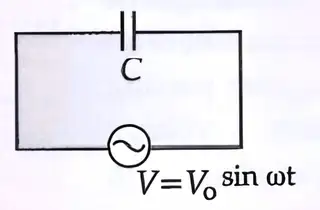
In a pure capacitive circuit, the current leads the voltage by 90°. The voltage and current are:
\( V = V_0 \sin \omega t \)
\( I = I_0 \sin (\omega t + \pi/2) \)
The average power consumed is also zero.
Phasor Diagrams
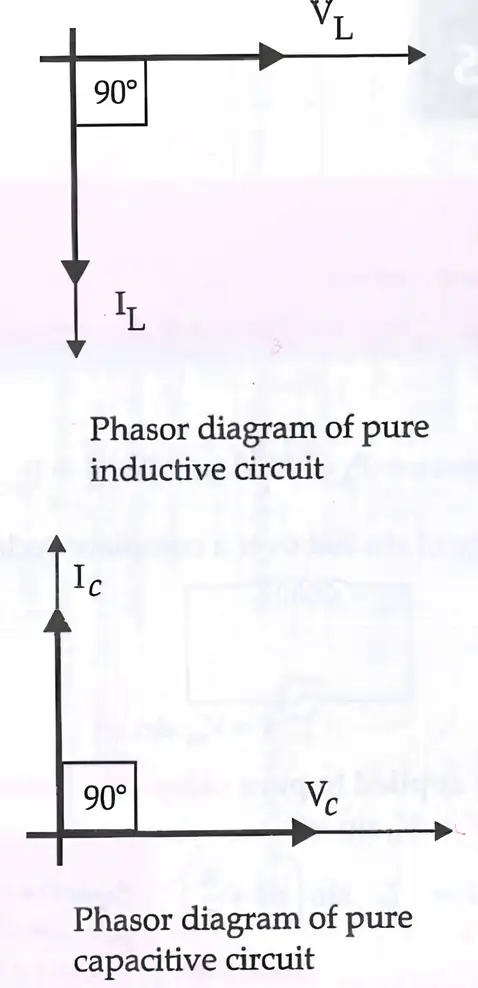
Phasor diagrams represent sinusoidal voltages and currents as rotating vectors (phasors) to illustrate phase relationships. In a pure inductive circuit, voltage leads current by 90°, while in a pure capacitive circuit, current leads voltage by 90°.
Reactance and Impedance
Resistance (R) opposes current flow in both AC and DC circuits and is measured in ohms (Ω). Reactance (X) is the opposition to AC caused by inductors and capacitors, also measured in ohms.
Inductive reactance is given by \( X_L = \omega L = 2 \pi f L \), where \( L \) is inductance.
Capacitive reactance is \( X_C = \frac{1}{\omega C} = \frac{1}{2 \pi f C} \), where \( C \) is capacitance.
Impedance (Z) is the total opposition to AC, combining resistance and reactance:
\( Z = \sqrt{R^2 + (X_L - X_C)^2} \)
Impedance is measured in ohms and determines the current in the circuit.
Solved Examples
Example 1: Calculate the rms value of an AC current with a peak value of 10 A.
Solution:
Given \( I_0 = 10 \) A
\( I_{rms} = \frac{I_0}{\sqrt{2}} = \frac{10}{1.414} = 7.07 \) A
Example 2: Find the inductive reactance of a coil with inductance 0.5 H at a frequency of 50 Hz.
Solution:
\( X_L = 2 \pi f L = 2 \times 3.1416 \times 50 \times 0.5 = 157.08 \) Ω
Example 3: Calculate the impedance of a circuit with resistance 30 Ω, inductive reactance 40 Ω, and capacitive reactance 10 Ω.
Solution:
Net reactance \( X = X_L - X_C = 40 - 10 = 30 \) Ω
Impedance \( Z = \sqrt{R^2 + X^2} = \sqrt{30^2 + 30^2} = \sqrt{900 + 900} = \sqrt{1800} = 42.43 \) Ω
Practice Set
- Level 1: Define alternating current and state its frequency in India.
- Level 2: Explain the phase relationship between current and voltage in a pure inductive circuit.
- Level 3: A series AC circuit has R = 20 Ω, L = 0.1 H, and C = 50 μF. Calculate the impedance and the phase angle at 50 Hz.
Answer Key
Level 1: Alternating current is an electric current that reverses direction periodically. In India, its frequency is 50 Hz.
Level 2: In a pure inductive circuit, the current lags the voltage by 90 degrees.
Level 3: Given: R = 20 Ω, L = 0.1 H, C = 50 μF = 50 × 10⁻⁶ F, f = 50 Hz
Calculate angular frequency \( \omega = 2 \pi f = 2 \times 3.1416 \times 50 = 314.16 \) rad/s
Inductive reactance \( X_L = \omega L = 314.16 \times 0.1 = 31.42 \) Ω
Capacitive reactance \( X_C = \frac{1}{\omega C} = \frac{1}{314.16 \times 50 \times 10^{-6}} = 63.66 \) Ω
Net reactance \( X = X_L - X_C = 31.42 - 63.66 = -32.24 \) Ω
Impedance \( Z = \sqrt{R^2 + X^2} = \sqrt{20^2 + (-32.24)^2} = \sqrt{400 + 1039.4} = \sqrt{1439.4} = 37.94 \) Ω
Phase angle \( \phi = \tan^{-1} \left( \frac{X}{R} \right) = \tan^{-1} \left( \frac{-32.24}{20} \right) = -58.3^\circ \)
The negative angle indicates current leads voltage.
LCR Series Circuit
Components and Circuit Description
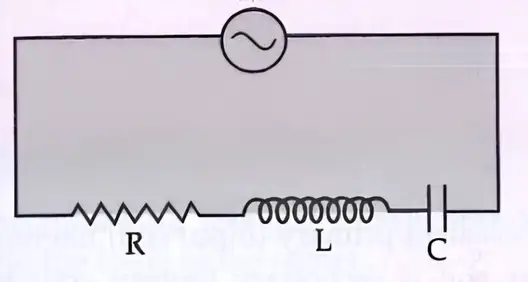
An LCR series circuit consists of a resistor (R), an inductor (L), and a capacitor (C) connected in series with an AC supply. The applied voltage is the sum of voltage drops across each component.
The voltage equation is:
\( V = V_0 \sin \omega t = RI + L \frac{dI}{dt} + \frac{1}{C} q \)
where \( q \) is the charge on the capacitor.
\( V = V_m \sin \omega t \)
Current and Impedance
The steady-state current is sinusoidal:
\( I = I_0 \sin (\omega t - \phi) \)
where \( I_0 = \frac{V_0}{Z} \) is the maximum current, and \( \phi \) is the phase difference between voltage and current.
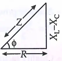
Impedance \( Z \) is given by:
\( Z = \sqrt{R^2 + (X_L - X_C)^2} \)
where \( X_L = \omega L \) and \( X_C = \frac{1}{\omega C} \) are inductive and capacitive reactances respectively.
The phase angle \( \phi \) is:
\( \tan \phi = \frac{X_L - X_C}{R} \)
Resonance in LCR Circuit
Resonance occurs when the inductive reactance equals the capacitive reactance:
\( X_L = X_C \)
At resonance, impedance is minimum and equals resistance \( Z = R \), and current is maximum:
\( I_0 = \frac{V_0}{R} \)
The resonance frequency is:
\( f = \frac{1}{2 \pi \sqrt{LC}} \)
The quality factor (Q) measures the sharpness of resonance:
\( Q = \frac{1}{R} \sqrt{\frac{L}{C}} \)
Power in AC Circuits
The instantaneous power is:
\( P = VI = V_0 I_0 \sin \omega t \sin (\omega t - \phi) \)
The average power over a cycle is:
\( P_{avg} = V_{rms} I_{rms} \cos \phi \)
where \( \cos \phi \) is the power factor.
Power factor varies between 0 and 1. When power factor is zero, the current is called wattless current, as in pure inductive or capacitive circuits.
Solved Examples
Example 1: Calculate the resonance frequency of an LCR circuit with \( L = 0.1 \) H and \( C = 50 \mu F \).
Solution:
\( f = \frac{1}{2 \pi \sqrt{LC}} = \frac{1}{2 \times 3.1416 \times \sqrt{0.1 \times 50 \times 10^{-6}}} = 71.2 \) Hz
Example 2: Find the impedance of a series LCR circuit with \( R = 30 \) Ω, \( L = 0.2 \) H, \( C = 100 \mu F \) at 50 Hz.
Solution:
\( \omega = 2 \pi f = 314.16 \) rad/s
\( X_L = \omega L = 314.16 \times 0.2 = 62.83 \) Ω
\( X_C = \frac{1}{\omega C} = \frac{1}{314.16 \times 100 \times 10^{-6}} = 31.83 \) Ω
\( X = X_L - X_C = 62.83 - 31.83 = 31 \) Ω
\( Z = \sqrt{R^2 + X^2} = \sqrt{30^2 + 31^2} = 43.27 \) Ω
Practice Set
- Level 1: Define impedance in an AC circuit.
- Level 2: Derive the expression for resonance frequency in an LCR circuit.
- Level 3: Calculate the quality factor of an LCR circuit with \( R = 10 \) Ω, \( L = 0.05 \) H, and \( C = 20 \mu F \).
Answer Key
Level 1: Impedance is the total opposition to the flow of alternating current in a circuit, combining resistance and reactance.
Level 2: At resonance, \( X_L = X_C \), so \( \omega L = \frac{1}{\omega C} \) which gives \( \omega^2 = \frac{1}{LC} \) and \( f = \frac{1}{2 \pi \sqrt{LC}} \).
Level 3: Given \( R = 10 \) Ω, \( L = 0.05 \) H, \( C = 20 \times 10^{-6} \) F
\( Q = \frac{1}{R} \sqrt{\frac{L}{C}} = \frac{1}{10} \sqrt{\frac{0.05}{20 \times 10^{-6}}} = 11.18 \)
AC Generator and Transformer
AC Generator
An AC generator converts mechanical energy into alternating electrical energy using electromagnetic induction. It consists of a coil (armature) rotating in a magnetic field between north and south poles of a magnet.
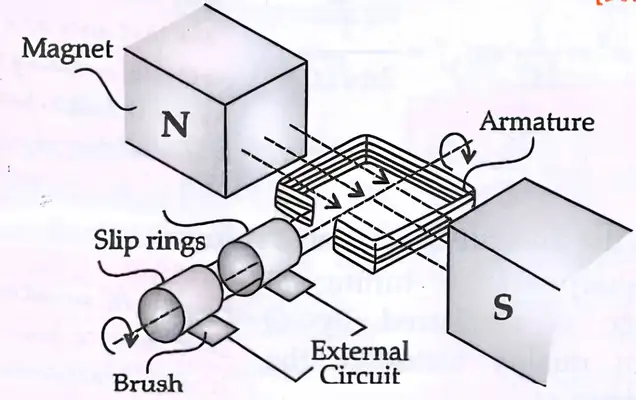
The induced emf in the coil is given by:
\( e = e_0 \sin \omega t = NBA \omega \sin \omega t \)
where \( N \) is the number of turns, \( B \) is the magnetic field strength, \( A \) is the area of the coil, and \( \omega \) is the angular velocity.
Transformer
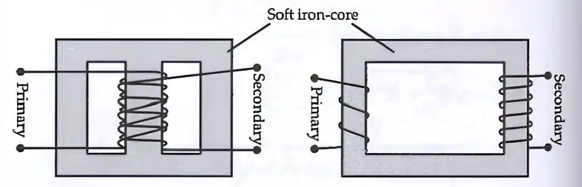
A transformer changes the amplitude of alternating voltages using mutual induction between two coils (primary and secondary) wound on a soft iron core.
The voltage and current ratios are related by:
\( \frac{V_s}{V_p} = \frac{I_p}{I_s} = \frac{N_s}{N_p} = k \)
where \( V_p, I_p, N_p \) are primary voltage, current, and turns; \( V_s, I_s, N_s \) are secondary values; and \( k \) is the transformation ratio.
Step-up transformers have \( k > 1 \), increasing voltage; step-down transformers have \( k < 1 \), decreasing voltage.
Efficiency \( \eta \) of a transformer is:
\( \eta = \frac{\text{Output power}}{\text{Input power}} = \frac{V_s I_s}{V_p I_p} \)
Typical efficiency is above 90%, with losses due to flux leakage, resistance, eddy currents, and hysteresis.
Solved Examples
Example 1: Calculate the peak emf of a generator with 100 turns, magnetic field 0.5 T, coil area 0.02 m², rotating at 50 Hz.
Solution:
\( \omega = 2 \pi f = 314.16 \) rad/s
\( e_0 = N B A \omega = 100 \times 0.5 \times 0.02 \times 314.16 = 314.16 \) V
Example 2: A transformer has 500 turns on the primary and 100 turns on the secondary. If the primary voltage is 240 V, find the secondary voltage.
Solution:
\( \frac{V_s}{V_p} = \frac{N_s}{N_p} \Rightarrow V_s = V_p \times \frac{N_s}{N_p} = 240 \times \frac{100}{500} = 48 \) V
Practice Set
- Level 1: What is the principle on which an AC generator works?
- Level 2: Explain the working of a transformer and state the formula relating voltages and turns.
- Level 3: Calculate the efficiency of a transformer if input power is 1000 W and output power is 940 W.
Answer Key
Level 1: An AC generator works on the principle of electromagnetic induction.
Level 2: A transformer works by mutual induction between two coils on a soft iron core. The voltages and turns are related by \( \frac{V_s}{V_p} = \frac{N_s}{N_p} \).
Level 3: Efficiency \( \eta = \frac{\text{Output power}}{\text{Input power}} \times 100 = \frac{940}{1000} \times 100 = 94\% \).
Quick Reference Table
Alternating Current: Current reversing direction periodically; frequency in India is 50 Hz.
RMS Values: \( I_{rms} = \frac{I_0}{\sqrt{2}} \), \( V_{rms} = \frac{V_0}{\sqrt{2}} \).
Reactance: \( X_L = \omega L \), \( X_C = \frac{1}{\omega C} \).
Impedance: \( Z = \sqrt{R^2 + (X_L - X_C)^2} \).
Resonance Frequency: \( f = \frac{1}{2 \pi \sqrt{LC}} \).
Power Factor: \( \cos \phi \), ratio of real power to apparent power.
AC Generator: \( e = N B A \omega \sin \omega t \).
Transformer: \( \frac{V_s}{V_p} = \frac{N_s}{N_p} = k \), efficiency \( \eta = \frac{V_s I_s}{V_p I_p} \).
Common Mistakes and Misconceptions
- Confusing peak value with rms value; rms is always \( 0.707 \) times peak.
- Assuming current and voltage are always in phase; phase difference depends on circuit elements.
- Neglecting reactance in AC circuits, leading to incorrect impedance calculations.
- Misunderstanding resonance condition; it occurs when inductive and capacitive reactances are equal.
- Believing transformers can work with DC; transformers require AC to operate.
Glossary
- Alternating Current (AC): Electric current that reverses direction periodically.
- Root Mean Square (RMS): Effective value of AC current or voltage.
- Reactance: Opposition to AC due to inductance or capacitance.
- Impedance: Total opposition to AC, combining resistance and reactance.
- Resonance: Condition in LCR circuit where inductive and capacitive reactances are equal.
- Power Factor: Ratio of real power to apparent power in AC circuits.
- Electromagnetic Induction: Generation of emf by changing magnetic flux.
- Transformer: Device that changes AC voltage levels using mutual induction.