Fundamentals of Ray Optics and Image Formation
Introduction to Light and Ray Optics
Understanding the Nature and Scope of Ray Optics
Light is a form of energy that allows us to perceive the world visually. The branch of physics that explores the characteristics, behavior, sources, and effects of light is known as optics. This field is divided mainly into two areas: physical optics, which examines the wave properties of light and its interaction with matter, and ray optics, also called geometrical optics, which studies light propagation assuming it travels in straight lines.
Ray optics focuses on the paths that light rays follow and is essential for understanding how images are formed by mirrors, lenses, and prisms. It simplifies light behavior by treating rays as straight lines, which helps analyze reflection and refraction phenomena.
Example: Explain why ray optics is a useful approximation for studying everyday optical devices.
Answer:
Ray optics assumes light travels in straight lines, simplifying analysis.
It accurately predicts image formation in mirrors and lenses where wave effects are negligible.
It helps design optical instruments like cameras and telescopes.
Key Terminology and Principles in Reflection
Essential Concepts Related to Mirrors
To understand image formation by mirrors, it is important to know several fundamental terms:
Pole: The central point on the mirror's surface where the principal axis passes.
Principal Axis: A straight line passing through the pole and the center of curvature.
Center of Curvature: The center of the sphere from which the mirror segment is taken.
Radius of Curvature: The radius of the sphere corresponding to the mirror.
Focus (Focal Point): The point where parallel rays converge after reflection.
Focal Length: The distance between the pole and the focus.
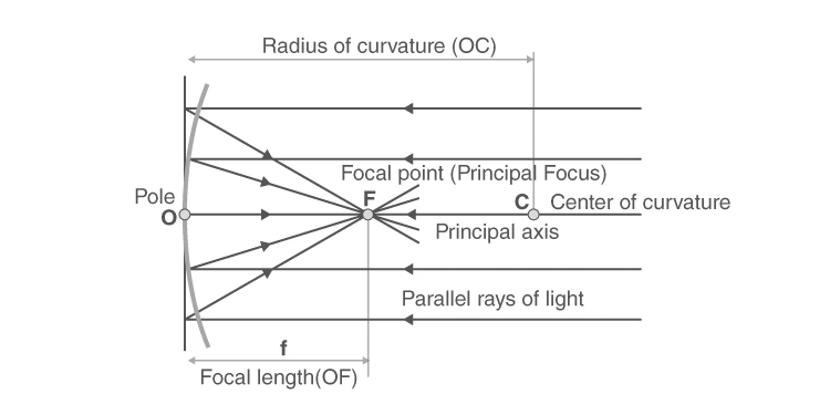
Diagram showing key terms associated with a mirror
Reflection and Its Governing Laws
Reflection occurs when light rays strike a polished surface and bounce back into the original medium. This phenomenon follows two fundamental laws:
The incident ray, reflected ray, and the normal at the point of incidence all lie in the same plane.
The angle of incidence is equal to the angle of reflection.
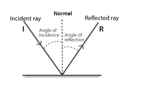
Visual representation of the laws of reflection
Example: A ray of light strikes a mirror at an angle of 30°. What is the angle between the incident ray and the reflected ray?
Solution:
Given angle of incidence \( i = 30^\circ \). By the law of reflection, angle of reflection \( r = 30^\circ \).
The angle between incident and reflected rays is \( i + r = 30^\circ + 30^\circ = 60^\circ \).
Refraction and Its Governing Principles
Understanding Refraction and Snell’s Law
Refraction is the bending of light rays when they pass obliquely from one transparent medium to another due to a change in their speed. This bending follows two main laws:
The incident ray, refracted ray, and the normal at the point of incidence lie in the same plane.
For a given pair of media and wavelength, the ratio of the sine of the angle of incidence to the sine of the angle of refraction is constant, known as Snell’s law:
\[ \frac{\sin i}{\sin r} = \text{constant} = \mu \]
Here, \( \mu \) is the refractive index of the second medium relative to the first.
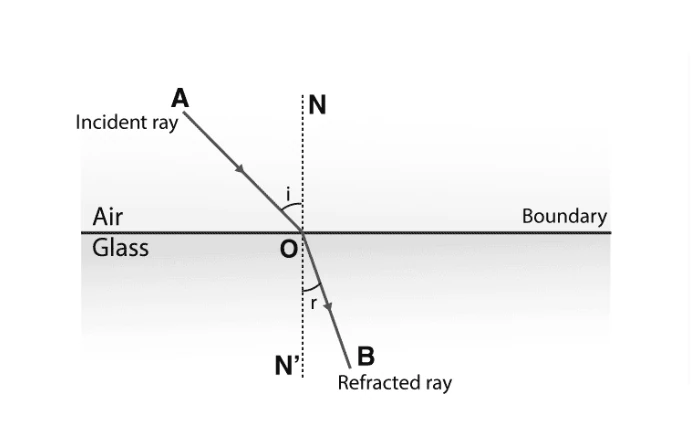
Diagram depicting the laws of refraction
Factors Influencing the Refractive Index
The refractive index depends on several factors:
The physical nature and temperature of the medium.
The wavelength or color of the incident light.
Presence of impurities in the medium can alter its refractive index.
The absolute refractive index is the ratio of light speed in vacuum to that in the medium, always greater than one.
Example: Light passes from air into water with an angle of incidence of \( 45^\circ \). If the refractive index of water with respect to air is 1.33, find the angle of refraction.
Solution:
Using Snell’s law:
\[ \mu = \frac{\sin i}{\sin r} \implies \sin r = \frac{\sin i}{\mu} = \frac{\sin 45^\circ}{1.33} = \frac{0.7071}{1.33} = 0.5315 \]
Therefore, \( r = \sin^{-1}(0.5315) \approx 32.1^\circ \).
Image Formation by Curved Mirrors
Types of Spherical Mirrors and Their Characteristics
Spherical mirrors are segments of a sphere and are classified based on the curvature of their reflecting surface:
Concave Mirror: Reflecting surface curves inward, converging light rays.
Convex Mirror: Reflecting surface curves outward, diverging light rays.
Image Formation by Concave Mirrors at Various Object Positions
The nature and position of images formed by a concave mirror depend on the object's location relative to the mirror's focal point (F) and center of curvature (C). Below are typical scenarios:
Object beyond C: Image is real, inverted, smaller, and formed between F and C.
Object at C: Image is real, inverted, and same size at C.
Object at F: Image formed at infinity; rays are parallel.
Object between F and C: Image is real, inverted, and magnified beyond C.
Object between F and pole: Image is virtual, erect, and magnified behind the mirror.
Object at infinity: Image formed at F, real, and highly diminished.
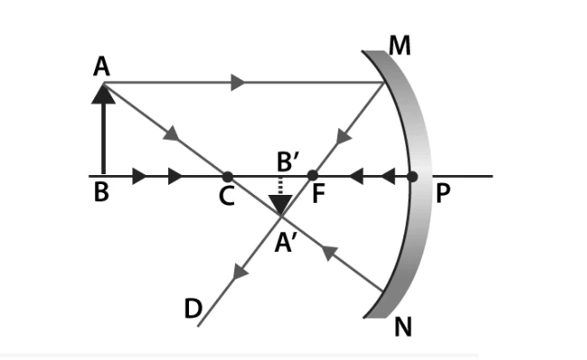
Object placed beyond center of curvature in concave mirror
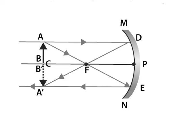
Object placed at center of curvature in concave mirror
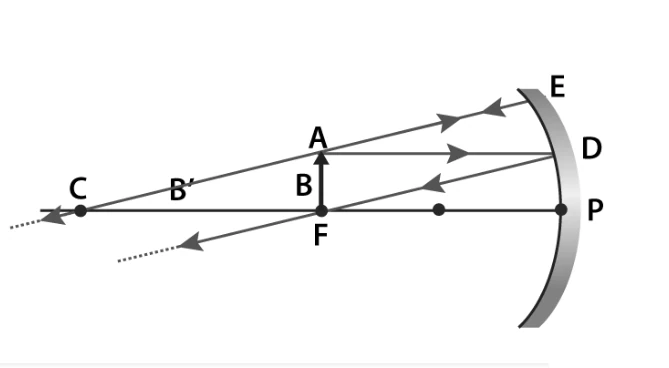
Object placed at focus in concave mirror
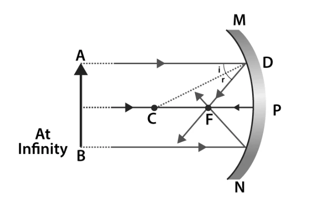
Object placed at infinity in concave mirror
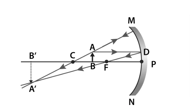
Object between center of curvature and focus in concave mirror
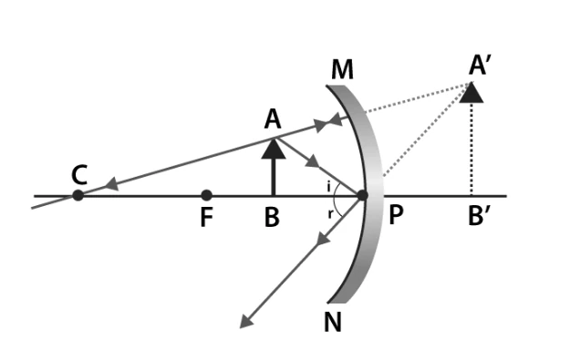
Object between focus and pole in concave mirror
Image Characteristics in Convex Mirrors
Convex mirrors always produce images that are virtual, erect, and diminished regardless of the object's position. The image appears behind the mirror.
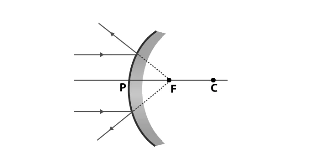
Image formed by convex mirror with object at infinity
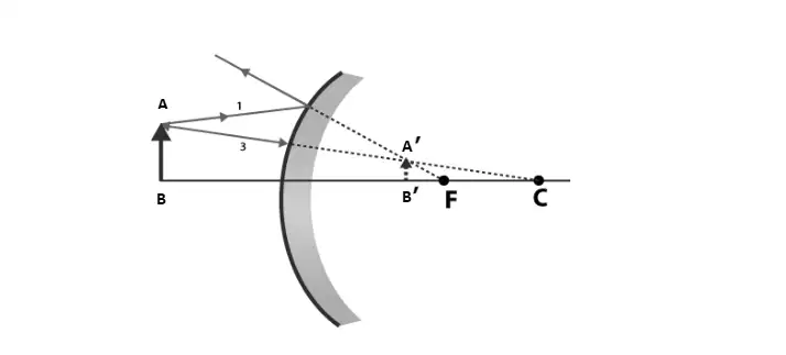
Image formed by convex mirror with object at finite distance
Example: An object is placed 30 cm in front of a concave mirror with radius of curvature 40 cm. Find the image distance, magnification, and nature of the image.
Solution:
Given: \( u = -30 \text{ cm} \), \( R = 40 \text{ cm} \), find \( v, m \).
Focal length \( f = \frac{R}{2} = \frac{40}{2} = 20 \text{ cm} \).
Using mirror formula:
\[ \frac{1}{f} = \frac{1}{v} + \frac{1}{u} \implies \frac{1}{20} = \frac{1}{v} - \frac{1}{30} \]
\[ \frac{1}{v} = \frac{1}{20} + \frac{1}{30} = \frac{3 + 2}{60} = \frac{5}{60} = \frac{1}{12} \]
So, \( v = 12 \text{ cm} \).
Magnification \( m = -\frac{v}{u} = -\frac{12}{-30} = 0.4 \) (positive, so image is erect).
The image is virtual, erect, and smaller than the object, located 12 cm behind the mirror.
Optical Lenses and Their Image Formation
Basic Lens Terminology and Types
A lens is an optical device with two refracting surfaces. When the thickness is small compared to the radius of curvature, it is called a thin lens. Lenses are categorized as:
Convex Lens (Converging): Thicker at the center, converges light rays.
Concave Lens (Diverging): Thinner at the center, diverges light rays.
Important terms related to lenses include:
Optical Centre (C): The central point of the lens where light passes undeviated.
Principal Axis: The line passing through the optical centre and centers of curvature.
Center of Curvature: The center of the sphere from which the lens surface is derived.
Focus (Focal Point): The point where parallel rays converge or appear to diverge.
Focal Length: Distance between the optical centre and the focus, equal to half the radius of curvature.
Image Formation by Convex Lenses
The position and nature of images formed by convex lenses vary with object placement:
Object between F and 2F: Image formed beyond 2F, real, inverted, and magnified.
Object at F: Image formed at infinity; rays are parallel.
Object between pole and F: Image is virtual, erect, and magnified on the same side.
Object at 2F: Image formed at 2F, real, inverted, and same size.
Object beyond 2F: Image formed between F and 2F, real, inverted, and diminished.
Object at infinity: Image formed at F, real, inverted, and highly diminished.
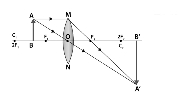
Object between F and 2F in convex lens
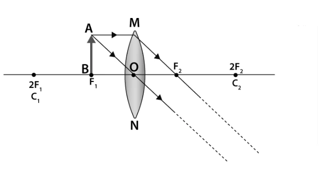
Object at focus in convex lens
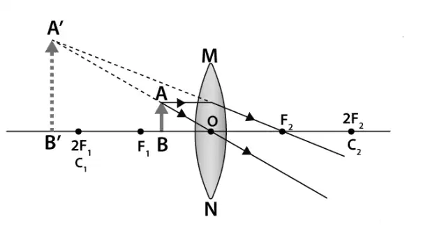
Object between focus and pole in convex lens
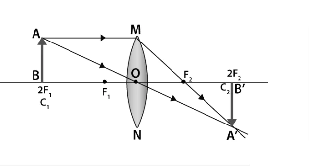
Object at 2F in convex lens
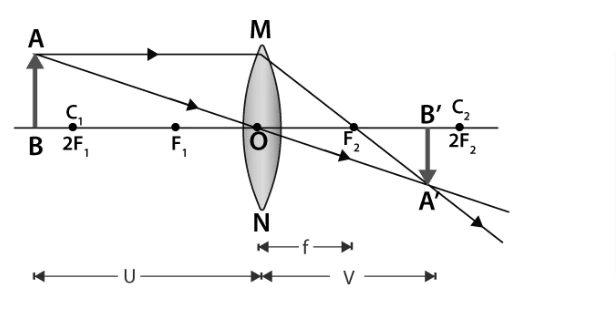
Object beyond 2F in convex lens
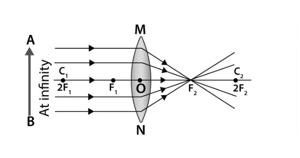
Object at infinity in convex lens
Image Formation by Concave Lenses
Concave lenses always produce virtual, erect, and diminished images regardless of the object's position. The image appears on the same side as the object.
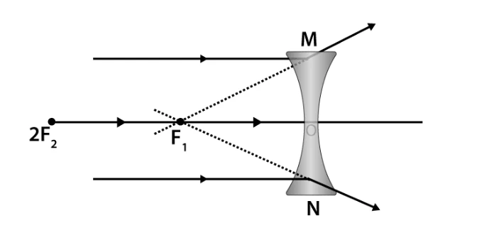
Object at infinity in concave lens
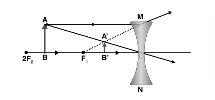
Object between infinity and optical centre in concave lens
Example: A convex lens has a focal length of 25 cm. An object is placed 15 cm from the lens. Find the image distance and magnification.
Solution:
Given: \( f = 25 \text{ cm} \), \( u = -15 \text{ cm} \).
Using lens formula:
\[ \frac{1}{f} = \frac{1}{v} - \frac{1}{u} \implies \frac{1}{25} = \frac{1}{v} - \frac{1}{-15} = \frac{1}{v} + \frac{1}{15} \]
\[ \frac{1}{v} = \frac{1}{25} - \frac{1}{15} = \frac{3 - 5}{75} = -\frac{2}{75} \]
So, \( v = -37.5 \text{ cm} \) (negative indicates virtual image on the same side as object).
Magnification \( m = \frac{v}{u} = \frac{-37.5}{-15} = 2.5 \) (image is magnified and erect).
Mathematical Relations in Lens and Mirror Optics
Mirror Formula and Magnification
The mirror formula relates the focal length \( f \), object distance \( u \), and image distance \( v \) as:
\[ \frac{1}{f} = \frac{1}{v} + \frac{1}{u} \]
Linear magnification \( m \) is defined as the ratio of image height to object height or image distance to object distance:
\[ m = \frac{h'}{h} = -\frac{v}{u} \]
If \( |m| < 1 \), the image is smaller; if \( |m| > 1 \), the image is larger. A negative magnification indicates an inverted image.
Lens Maker’s Formula
The lens maker’s formula connects the focal length \( f \), refractive index \( \mu \), and radii of curvature \( R_1 \) and \( R_2 \) of the lens surfaces:
\[ \frac{1}{f} = (\mu - 1) \left( \frac{1}{R_1} - \frac{1}{R_2} \right) \]
Power of a Lens
The power \( P \) of a lens is the reciprocal of its focal length (in meters):
\[ P = \frac{1}{f} \]
The unit of power is diopter (D), where \( 1 \text{ D} = 1 \text{ m}^{-1} \).
Example: A concave mirror has a radius of curvature of 30 cm. Calculate its focal length and the power of the mirror.
Solution:
Focal length \( f = \frac{R}{2} = \frac{30}{2} = 15 \text{ cm} = 0.15 \text{ m} \).
Power \( P = \frac{1}{f} = \frac{1}{0.15} = 6.67 \text{ D} \).
Since it is a concave mirror, the focal length is negative, so power is \( -6.67 \text{ D} \).
Summary of Key Concepts in Ray Optics
Concept | Definition/Formula | Notes |
|---|---|---|
Reflection | Angle of incidence = Angle of reflection | Occurs on polished surfaces |
Refraction | \( \frac{\sin i}{\sin r} = \mu \) (Snell’s Law) | Bending of light at interface of two media |
Mirror Formula | \( \frac{1}{f} = \frac{1}{v} + \frac{1}{u} \) | Relates focal length, image and object distances |
Magnification | \( m = -\frac{v}{u} = \frac{h'}{h} \) | Indicates size and orientation of image |
Lens Maker’s Formula | \( \frac{1}{f} = (\mu - 1) \left( \frac{1}{R_1} - \frac{1}{R_2} \right) \) | Used to design lenses with specific focal lengths |
Power of Lens | \( P = \frac{1}{f} \) | Measured in diopters (D) |
Concave Mirror | Focuses light; real or virtual images | Reflecting surface curves inward |
Convex Mirror | Diverges light; virtual, diminished images | Reflecting surface curves outward |
Convex Lens | Converges light; real or virtual images | Thicker at center |
Concave Lens | Diverges light; virtual, diminished images | Thinner at center |
Glossary of Important Terms
Term | Meaning |
|---|---|
Focal Length | Distance between the pole and the focus of a mirror or lens |
Principal Axis | Line passing through the center of curvature and pole or optical center |
Center of Curvature | Center of the sphere from which a mirror or lens is a part |
Radius of Curvature | Radius of the sphere corresponding to the mirror or lens |
Magnification | Ratio of image height to object height |
Refractive Index | Ratio of speed of light in vacuum to that in a medium |
Optical Centre | Point in a lens through which light passes undeviated |
Concave Mirror | Mirror with inward curved reflecting surface |
Convex Mirror | Mirror with outward curved reflecting surface |
Lens Power | Inverse of focal length, measured in diopters |
Frequently Asked Questions
What is the main assumption in ray optics?
Ray optics assumes that light travels in straight lines, which simplifies the analysis of reflection and refraction.
How does a concave mirror differ from a convex mirror?
A concave mirror curves inward and can form real or virtual images, while a convex mirror curves outward and always forms virtual, diminished images.
What is the significance of the focal length of a lens?
The focal length determines where parallel rays converge or appear to diverge, affecting image formation and magnification.
How is magnification related to image orientation?
A positive magnification indicates an erect image, while a negative magnification indicates an inverted image.
What does the lens maker’s formula help determine?
It helps calculate the focal length of a lens based on its refractive index and the curvature of its surfaces, aiding lens design.