Magnetic Fields Around Current-Carrying Conductors
Fundamentals of Magnetic Fields Generated by Electric Currents
Understanding Magnetic Fields Created by Moving Charges
A magnetic field is a spatial region where magnetic forces can be detected. This phenomenon arises primarily due to moving electric charges or magnetic materials. The concept was first scientifically observed in the early 1800s when Hans Christian Ørsted discovered that an electric current flowing through a conductor produces a magnetic effect around it. This discovery linked electricity and magnetism, explaining earlier observations such as compass needle deflections during lightning storms.
Electric current, defined as the rate at which charge flows through a conductor, generates a magnetic field whose strength depends on the magnitude of the current and the distance from the conductor. The magnetic field is a vector quantity, denoted by \( \mathbf{B} \), possessing both magnitude and direction. The direction of the magnetic field lines is perpendicular to the conductor and can be determined using the right-hand thumb rule: if the thumb points in the direction of current, the curled fingers indicate the magnetic field's circular direction around the wire.
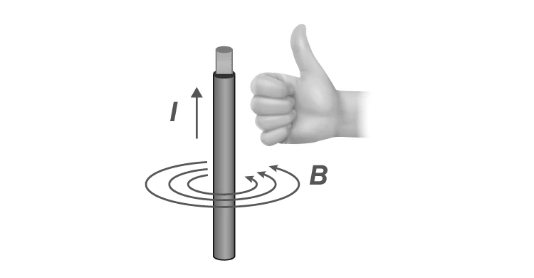
Magnetic field lines encircling a current-carrying wire
Example Problem
Calculate the magnetic field at a point located 4 cm from a long straight wire carrying a current of 6 A. Use the formula for magnetic field around a straight conductor:
\[ B = \frac{\mu_0 I}{2 \pi r} \]
where \( \mu_0 = 4\pi \times 10^{-7} \text{ T·m/A} \), \( I \) is current, and \( r \) is distance from the wire.
Solution:
Given: \( I = 6 \text{ A} \), \( r = 4 \text{ cm} = 0.04 \text{ m} \)
Substitute values:
\[ B = \frac{4\pi \times 10^{-7} \times 6}{2 \pi \times 0.04} = \frac{24\pi \times 10^{-7}}{2 \pi \times 0.04} \]
Simplify numerator and denominator:
\[ B = \frac{24 \times 10^{-7}}{2 \times 0.04} = \frac{24 \times 10^{-7}}{0.08} = 3 \times 10^{-5} \text{ T} \]
Therefore, the magnetic field at 4 cm from the wire is \( 3 \times 10^{-5} \text{ Tesla} \).
Properties of Magnetic Fields Around Conductors Carrying Current
Key Features of Magnetic Fields Produced by Electric Currents
The magnetic field generated by a current-carrying conductor exhibits several important characteristics:
The magnetic field lines form concentric circles around the conductor.
These field lines lie in planes perpendicular to the length of the conductor.
Reversing the direction of current flow reverses the magnetic field's direction.
The magnetic field strength is directly proportional to the current's magnitude.
The field strength decreases as the distance from the conductor increases, following an inverse relationship.
Magnetism plays a crucial role in many technologies, from small electric motors in toys to large-scale applications like bullet trains and spacecraft propulsion systems. Understanding these properties is essential for grasping how electromagnetic devices function.
Example Problem
A wire carries a current of 8 A. What will be the magnetic field strength at a point 10 cm away from the wire? Also, what happens to the magnetic field if the current is reversed?
Solution:
Given: \( I = 8 \text{ A} \), \( r = 10 \text{ cm} = 0.10 \text{ m} \)
Using the formula:
\[ B = \frac{\mu_0 I}{2 \pi r} = \frac{4\pi \times 10^{-7} \times 8}{2 \pi \times 0.10} = \frac{32\pi \times 10^{-7}}{2 \pi \times 0.10} \]
Simplify:
\[ B = \frac{32 \times 10^{-7}}{0.20} = 1.6 \times 10^{-5} \text{ T} \]
If the current direction is reversed, the magnetic field direction also reverses, meaning the circular field lines will rotate in the opposite direction around the wire.
Determining Magnetic Field Directions and Practical Applications
Rules for Identifying Magnetic Poles and Force Directions
To identify the direction of the magnetic field and poles around a current-carrying conductor, Maxwell’s corkscrew rule or the right-hand thumb rule is used. When the thumb points along the current, the curl of the fingers shows the magnetic field's circular direction. The end where the field lines emerge is considered the north pole.
When a magnetic field acts perpendicular to a current-carrying conductor, the conductor experiences a force. Fleming’s left-hand rule helps determine the force's direction: the thumb represents force, the forefinger the magnetic field, and the middle finger the current.
Visualizing Maxwell’s corkscrew rule for magnetic field direction
Fleming’s left-hand rule to find force direction on conductor
Example Problem
A conductor carrying a current of 5 A is placed in a magnetic field of strength \( 0.2 \text{ T} \) perpendicular to the conductor. If the conductor length within the field is 0.3 m, calculate the magnitude of the force acting on the conductor.
Solution:
The force on a current-carrying conductor in a magnetic field is given by:
\[ F = B I L \sin \theta \]
Since the field is perpendicular, \( \theta = 90^\circ \) and \( \sin 90^\circ = 1 \).
Given: \( B = 0.2 \text{ T} \), \( I = 5 \text{ A} \), \( L = 0.3 \text{ m} \)
Calculate force:
\[ F = 0.2 \times 5 \times 0.3 = 0.3 \text{ N} \]
The force acting on the conductor is \( 0.3 \text{ Newtons} \), and its direction can be found using Fleming’s left-hand rule.
Quick Reference Summary
Concept | Key Points |
|---|---|
Magnetic Field | Region where magnetic forces act; produced by moving charges |
Right-Hand Thumb Rule | Thumb points current; curled fingers show magnetic field direction |
Magnetic Field Strength | Proportional to current, inversely proportional to distance from wire |
Maxwell’s Corkscrew Rule | Determines north pole direction of magnetic field around conductor |
Fleming’s Left-Hand Rule | Used to find force direction on current-carrying conductor in magnetic field |
Force on Conductor | \( F = BIL \sin \theta \), force depends on magnetic field, current, length, and angle |
Glossary of Important Terms
Term | Definition |
|---|---|
Magnetic Field (\( \mathbf{B} \)) | A vector field representing magnetic influence around magnets or currents |
Electric Current | Flow of electric charge through a conductor, measured in amperes (A) |
Right-Hand Thumb Rule | Rule to find magnetic field direction around a current-carrying wire |
Maxwell’s Corkscrew Rule | Method to determine magnetic pole direction using a corkscrew analogy |
Fleming’s Left-Hand Rule | Technique to find force direction on a conductor in a magnetic field |
Magnetic Force | Force exerted on moving charges or current-carrying conductors in magnetic fields |
Magnetic Pole | Region where magnetic field lines emerge (north) or enter (south) |
Magnetic Field Lines | Imaginary lines representing the direction and strength of magnetic fields |
Permeability of Free Space (\( \mu_0 \)) | Constant \( 4\pi \times 10^{-7} \text{ T·m/A} \) used in magnetic field calculations |
Force on Conductor | Force experienced by a current-carrying wire in a magnetic field, calculated by \( F = BIL \sin \theta \) |
Frequently Asked Questions
What defines a magnetic field?
A magnetic field is a region around a magnet or current-carrying conductor where magnetic forces can be detected.
How is electric current related to magnetic fields?
Electric current, which is moving electric charge, generates a magnetic field around the conductor through which it flows.
What is the significance of the right-hand thumb rule?
This rule helps determine the direction of the magnetic field around a current-carrying wire by aligning the thumb with current direction and curling the fingers.
How does reversing current affect the magnetic field?
Reversing the current direction reverses the magnetic field's direction around the conductor.
How can the force on a conductor in a magnetic field be calculated?
The force is given by \( F = BIL \sin \theta \), where \( B \) is magnetic field strength, \( I \) is current, \( L \) is conductor length, and \( \theta \) is the angle between current and magnetic field.