Fundamentals and Applications of Alternating Current
Understanding Alternating Current and Its Generation
Concept and Characteristics of Alternating Current
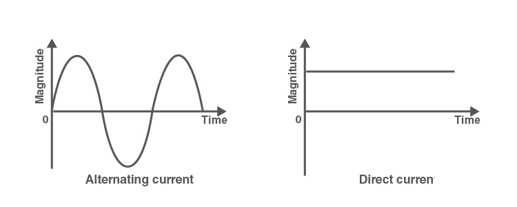
Alternating current (AC) is an electric current that periodically reverses its direction and varies in magnitude over time. Unlike direct current (DC), which flows steadily in one direction, AC continuously changes polarity, creating cycles of positive and negative values. This behavior allows the current to oscillate between zero and its peak values in both directions repeatedly.
The graph below illustrates the typical behavior of AC, where the current starts at zero, rises to a maximum positive value, returns to zero, then reverses to a maximum negative value before completing one full cycle. This pattern repeats continuously, defining the alternating nature of the current.
Alternating current is commonly paired with alternating voltage, and one of its key advantages is the ease with which its voltage level can be transformed using transformers, facilitating efficient power transmission over long distances.
Methods of Producing Alternating Current
Alternating current is primarily generated by devices called alternators, which convert mechanical energy into electrical energy based on Faraday’s law of electromagnetic induction. A simple AC generator consists of a rectangular coil rotating between the poles of a magnet, inducing an alternating voltage and current in the coil.
In practical electrical systems, AC is delivered through three wires:
- Hot wire: Carries the current to the load.
- Neutral wire: Connected to earth, providing a return path for current.
- Ground wire: Also connected to earth, it safeguards against electric shocks by connecting metallic parts of equipment to the ground.
Example: Calculating the Frequency of an AC Generator
Problem: A coil in an AC generator completes 3600 rotations in one minute. Determine the frequency of the alternating current produced.
Solution:
The frequency \( f \) is the number of cycles per second.
Number of rotations per minute = 3600
Convert to rotations per second:
\[ f = \frac{3600}{60} = 60 \text{ Hz} \]
Therefore, the AC generator produces current at a frequency of 60 Hz.
Waveform Properties and Measurement of Alternating Current
Shape and Parameters of AC Waveforms
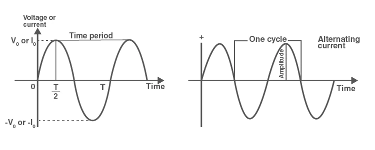
The most common form of AC waveform is sinusoidal, where the current or voltage varies smoothly and periodically. Key terms related to AC waveforms include:
- Period (T): The time taken to complete one full cycle.
- Frequency (f): The number of cycles per second, measured in hertz (Hz).
- Amplitude: The peak value of the current or voltage in either direction.
Besides sinusoidal waves, AC can also take triangular or square waveforms, especially in electronic circuits such as oscillators and audio amplifiers.
Calculating Average and RMS Values of AC
The average value of an AC over a full cycle is zero because the positive and negative halves cancel each other out. However, the average of the absolute values over a half cycle is used to represent the effective value for practical purposes.
The root mean square (RMS) value is a crucial measure that represents the equivalent DC value producing the same heating effect as the AC. It is calculated as the square root of the mean of the squares of instantaneous values over a cycle.
Example: Determining RMS Value from Peak Voltage
Problem: An AC voltage has a peak value of 170 V. Calculate its RMS voltage.
Solution:
The RMS voltage \( V_{\text{rms}} \) is related to the peak voltage \( V_m \) by:
\[ V_{\text{rms}} = \frac{V_m}{\sqrt{2}} = \frac{170}{\sqrt{2}} \approx 120.2 \text{ V} \]
Thus, the RMS voltage is approximately 120.2 volts.
Behavior of AC in Different Circuit Elements
AC in Purely Resistive Circuits
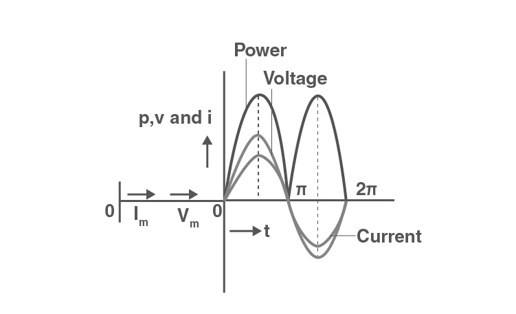
In circuits containing only resistance, the current and voltage vary sinusoidally and remain in phase, meaning their peaks and zero crossings occur simultaneously. The resistor dissipates electrical energy as heat, and there is no phase difference between voltage and current.
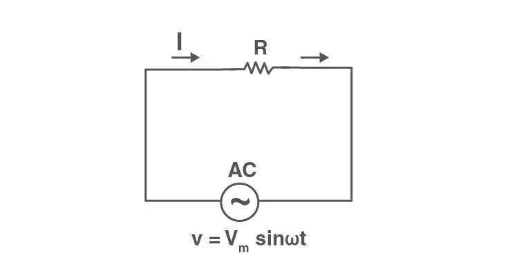
Mathematically, if the supply voltage is given by
\[ v = V_m \sin \omega t \]
then the current through the resistor is
\[ i = \frac{V_m}{R} \sin \omega t = I_m \sin \omega t \]
where \( I_m = \frac{V_m}{R} \) is the maximum current. Since both voltage and current have the same phase angle, the phase difference is zero.
AC Response in Pure Inductive Circuits
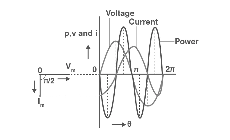
In circuits with only inductance, the current lags behind the voltage by 90 degrees (or \( \pi/2 \) radians). The inductor stores energy in its magnetic field and opposes changes in current, causing this phase shift.
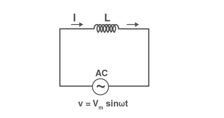
The applied voltage is
\[ v = V_m \sin \omega t \]
The induced emf in the inductor is
\[ E = -L \frac{di}{dt} \]
Equating applied voltage and induced emf:
\[ V_m \sin \omega t = L \frac{di}{dt} \]
Integrating, the current is
\[ i = -\frac{V_m}{\omega L} \cos \omega t = \frac{V_m}{\omega L} \sin \left( \omega t - \frac{\pi}{2} \right) \]
Here, the inductive reactance is \( X_L = \omega L \), and the maximum current is
\[ I_m = \frac{V_m}{X_L} \]
This confirms that current lags voltage by 90 degrees in a pure inductive circuit.
AC Behavior in Pure Capacitive Circuits
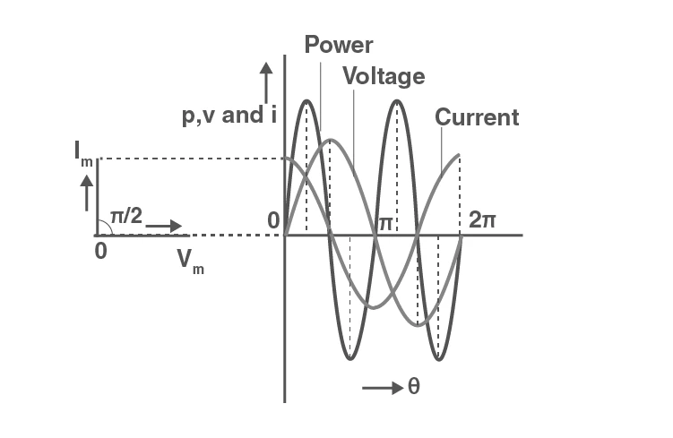
In circuits containing only a capacitor, the current leads the voltage by 90 degrees. The capacitor stores energy in its electric field and charges or discharges as the voltage changes.
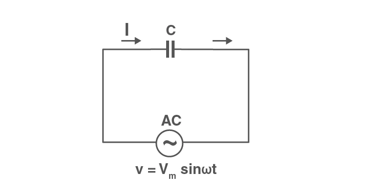
Given the applied voltage
\[ v = V_m \sin \omega t \]
The charge on the capacitor is
\[ q = C v = C V_m \sin \omega t \]
The current is the rate of change of charge:
\[ i = \frac{dq}{dt} = C V_m \omega \cos \omega t = C V_m \omega \sin \left( \omega t + \frac{\pi}{2} \right) \]
Defining capacitive reactance as \( X_C = \frac{1}{\omega C} \), the maximum current is
\[ I_m = \frac{V_m}{X_C} \]
This shows that current leads voltage by 90 degrees in a pure capacitive circuit.
Example: Phase Difference in an Inductive Circuit
Problem: An AC voltage \( v = 100 \sin 314 t \) volts is applied to a pure inductor of inductance 0.1 H. Calculate the maximum current and write the expression for current.
Solution:
Angular frequency \( \omega = 314 \text{ rad/s} \)
Inductive reactance:
\[ X_L = \omega L = 314 \times 0.1 = 31.4 \ \Omega \]
Maximum current:
\[ I_m = \frac{V_m}{X_L} = \frac{100}{31.4} \approx 3.18 \text{ A} \]
Current expression:
\[ i = I_m \sin \left( \omega t - \frac{\pi}{2} \right) = 3.18 \sin \left( 314 t - \frac{\pi}{2} \right) \text{ A} \]
This confirms the current lags voltage by 90 degrees in the inductive circuit.
Summary and Key Concepts of Alternating Current
| Term | Definition | Formula / Notes |
|---|---|---|
| Alternating Current (AC) | Current that reverses direction periodically | Varies sinusoidally with time |
| Period (T) | Time for one complete cycle | \( T = \frac{1}{f} \) |
| Frequency (f) | Number of cycles per second | Measured in hertz (Hz) |
| Amplitude | Maximum value of current or voltage | Peak value \( V_m \) or \( I_m \) |
| RMS Value | Effective value producing same heating effect as DC | \( V_{\text{rms}} = \frac{V_m}{\sqrt{2}} \) |
| Inductive Reactance (\( X_L \)) | Opposition to current in inductors | \( X_L = \omega L \) |
| Capacitive Reactance (\( X_C \)) | Opposition to current in capacitors | \( X_C = \frac{1}{\omega C} \) |
| Phase Difference | Angular difference between voltage and current | 0° in resistive, 90° lag in inductive, 90° lead in capacitive |
| Phasor Diagram | Graphical representation of phase relationships | Shows lead, lag, and in-phase conditions |
| Alternator | Device generating AC by electromagnetic induction | Converts mechanical to electrical energy |
Glossary of Key Terms
| Term | Meaning |
|---|---|
| Alternating Current (AC) | Electric current that reverses direction periodically |
| Direct Current (DC) | Electric current flowing in one direction only |
| Period | Time taken to complete one full cycle of AC |
| Frequency | Number of AC cycles per second, measured in hertz |
| Amplitude | Maximum instantaneous value of current or voltage |
| RMS Value | Root mean square value representing effective AC magnitude |
| Inductive Reactance | Resistance offered by an inductor to AC |
| Capacitive Reactance | Resistance offered by a capacitor to AC |
| Phasor | Vector representing magnitude and phase of sinusoidal quantities |
| Alternator | Machine that produces alternating current by electromagnetic induction |
Frequently Asked Questions on Alternating Current
What defines the period of an alternating current?
The period is the duration required for the AC to complete one full cycle of its waveform.
How is the frequency of AC related to its period?
Frequency is the reciprocal of the period, representing how many cycles occur per second.
What is the significance of the RMS value in AC circuits?
The RMS value indicates the equivalent DC value that would produce the same heating effect as the AC.
Why does current lag voltage in an inductive AC circuit?
Because the inductor opposes changes in current by generating an emf, causing the current to reach its peak after the voltage.
What advantage does AC have over DC in power transmission?
AC can be easily transformed to higher or lower voltages, enabling efficient long-distance power transmission with minimal losses.