Comprehensive Guide to Moving Coil Galvanometers
Fundamentals and Design of Moving Coil Galvanometers
Understanding the Moving Coil Galvanometer
A moving coil galvanometer is a precise instrument designed to detect and measure very small electric currents, often in the microampere range. It operates on the principle that a current-carrying coil placed within a magnetic field experiences a torque proportional to the current flowing through it. This deflection is then used to quantify the current magnitude.
Historically, various types of galvanometers have been developed, including tangent, astatic, mirror, and ballistic galvanometers. However, the moving coil galvanometer, also known as the D’Arsonval or Weston galvanometer, remains the most widely used due to its sensitivity and accuracy.
Structural Components and Assembly
The core of the moving coil galvanometer consists of a rectangular coil made from fine, insulated copper wire wound on a metallic frame. This coil is suspended so it can rotate freely about a fixed axis within a uniform radial magnetic field. The suspension is achieved using a phosphor-bronze strip connected to a torsion head, which provides both electrical connectivity and mechanical support.
To enhance the magnetic field strength and ensure it remains radial, a cylindrical soft iron core is placed symmetrically inside the coil. The coil's lower end is attached to a phosphor-bronze spring that produces a restoring torque opposing the coil's deflection. A mirror attached to the suspension wire, combined with a lamp and scale setup, allows precise measurement of the coil's angular displacement.
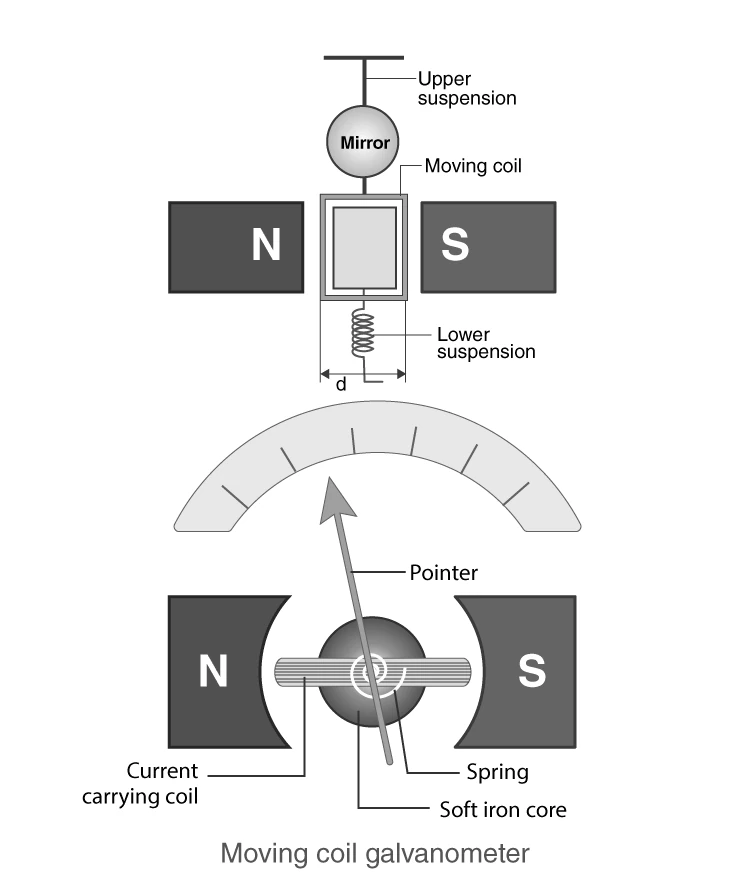
Illustration of Moving Coil Galvanometer Construction
Illustrative Example: Role of the Soft Iron Core
Question: Why is a cylindrical soft iron core introduced inside the moving coil galvanometer?
Answer: The soft iron core intensifies the magnetic field within the coil, thereby increasing the galvanometer's sensitivity. It also ensures the magnetic field remains radial, maintaining a constant angle between the coil plane and magnetic lines during rotation, which is crucial for accurate measurement.
Operational Principles and Performance Metrics
Mechanics Behind the Coil's Deflection
Consider a rectangular coil with n turns, each having an area \( A = l \times b \), where \( l \) and \( b \) are the coil's length and breadth respectively. When a current \( I \) passes through this coil placed in a uniform magnetic field \( B \), the coil experiences a magnetic torque \( \tau \).
The sides of the coil parallel to the magnetic field do not experience force, while the perpendicular sides experience forces of magnitude \( F = BIl \) in opposite directions, creating a couple that produces torque.
The torque on a single turn is:
\[ \tau = F \times b = BIlb = BIA \]
For \( n \) turns, the total torque is:
\[ \tau = nIAB \]
This torque causes the coil to rotate, twisting the suspension strip and spring, which exerts a restoring torque \( k\theta \), where \( k \) is the torsional constant and \( \theta \) is the angular deflection.
At equilibrium:
\[ k\theta = nIAB \]
Rearranging, the deflection angle is proportional to the current:
\[ \theta = \frac{nAB}{k} I \]
This linear relationship allows the galvanometer to measure current by observing the coil's deflection.
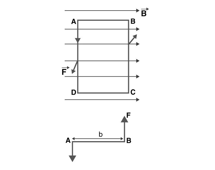
Forces on Coil Sides in Magnetic Field
Example Problem: Calculating Coil Deflection
Problem: A coil with 50 turns and an area of \( 2 \times 10^{-4} \text{ m}^2 \) is suspended in a magnetic field of strength \( 0.3 \text{ T} \). If the torsional constant of the suspension spring is \( 0.02 \text{ Nm/rad} \), find the deflection angle when a current of \( 5 \times 10^{-4} \text{ A} \) passes through the coil.
Solution:
Given: \( n = 50 \), \( A = 2 \times 10^{-4} \text{ m}^2 \), \( B = 0.3 \text{ T} \), \( k = 0.02 \text{ Nm/rad} \), \( I = 5 \times 10^{-4} \text{ A} \)
Using the formula:
\[ \theta = \frac{nAB}{k} I = \frac{50 \times 0.3 \times 2 \times 10^{-4}}{0.02} \times 5 \times 10^{-4} \]
\[ = \frac{50 \times 0.3 \times 2 \times 10^{-4} \times 5 \times 10^{-4}}{0.02} = \frac{1.5 \times 10^{-3}}{0.02} = 0.075 \text{ radians} \]
Converting to degrees:
\[ 0.075 \times \frac{180}{\pi} \approx 4.3^\circ \]
The coil deflects approximately \( 4.3^\circ \) for the given current.
Enhancing Sensitivity and Practical Applications
Quantifying Sensitivity and Its Influencing Factors
The sensitivity of a moving coil galvanometer is defined as the ratio of the change in deflection angle to the change in current:
\[ S = \frac{d\theta}{dI} \]
Higher sensitivity means a larger deflection for a small current. Sensitivity can be categorized as:
Current Sensitivity: Deflection per unit current, given by \( \frac{\theta}{I} = \frac{nAB}{k} \).
Voltage Sensitivity: Deflection per unit voltage, expressed as \( \frac{\theta}{V} = \frac{nAB}{kR} \), where \( R \) is the coil's resistance.
The figure of merit of a galvanometer is the current required for full-scale deflection divided by the number of scale divisions, essentially the inverse of current sensitivity.
Factors affecting sensitivity include:
Number of coil turns
Coil area
Magnetic field strength
Torsional constant of the suspension spring
Example Question: Relationship Between Current and Voltage Sensitivity
Question: Does increasing the current sensitivity of a moving coil galvanometer always increase its voltage sensitivity? Explain.
Answer: Not necessarily. While current sensitivity depends on coil parameters, increasing the number of turns to improve current sensitivity also increases coil resistance. Since voltage sensitivity is inversely proportional to resistance, the overall voltage sensitivity may remain unchanged despite higher current sensitivity.
Practical Uses of the Moving Coil Galvanometer
Due to its high sensitivity, the moving coil galvanometer is widely used to detect small currents in circuits. It is commonly employed in Wheatstone bridge setups to identify null points where no current flows through the galvanometer, indicating balanced conditions.
By adding appropriate resistances, the galvanometer can be adapted to function as:
Ammeter: Connected in parallel with a low-value shunt resistance to measure current.
Voltmeter: Connected in series with a high resistance to measure voltage.
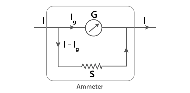
Galvanometer Modified as an Ammeter with Shunt Resistance
Example Calculation: Ammeter Current Range
Problem: A galvanometer with resistance \( 120 \Omega \) and full-scale deflection current of \( 80 \mu A \) is converted into an ammeter by connecting a shunt resistance in parallel. If the shunt resistance is \( 0.15 \Omega \), calculate the maximum current the ammeter can measure.
Solution:
Given: \( R_G = 120 \Omega \), \( I_G = 80 \times 10^{-6} \text{ A} \), \( R_S = 0.15 \Omega \)
Total current \( I \) is related by:
\[ R_G I_G = R_S (I - I_G) \]
Rearranged:
\[ I = I_G \left(1 + \frac{R_G}{R_S}\right) = 80 \times 10^{-6} \times \left(1 + \frac{120}{0.15}\right) \]
\[ = 80 \times 10^{-6} \times (1 + 800) = 80 \times 10^{-6} \times 801 = 0.06408 \text{ A} \]
The ammeter can measure up to approximately \( 64 \text{ mA} \).
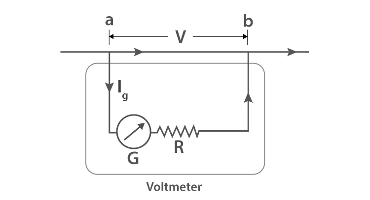
Galvanometer Modified as a Voltmeter with Series Resistance
Example Calculation: Voltmeter Range Setup
Problem: A galvanometer with coil resistance \( 50 \Omega \) shows full-scale deflection at \( 2 \text{ mA} \). Determine the value of series resistance required to convert it into a voltmeter with a range of 0–10 V.
Solution:
<
Given: \( R_G = 50 \Omega \), \( I_G = 2 \times 10^{-3} \text{ A} \), \( V = 10 \text{ V} \)
Using:
\[ V = I_G (R_G + R) \]
Rearranged to find \( R \):
\[ R = \frac{V}{I_G} - R_G = \frac{10}{2 \times 10^{-3}} - 50 = 5000 - 50 = 4950 \Omega \]
A series resistance of \( 4950 \Omega \) is needed.
Advantages, Limitations, and Additional Insights
Strengths of Moving Coil Galvanometers
Exceptional sensitivity to detect very small currents.
Minimal interference from external magnetic fields due to radial field design.
High torque-to-weight ratio enabling precise deflections.
Reliable and accurate readings with stable mechanical construction.
Limitations to Consider
Restricted to measuring direct currents only; cannot measure alternating currents.
Accuracy may degrade over time due to mechanical wear, magnet aging, or spring fatigue.
Requires careful calibration and maintenance to ensure consistent performance.
Moving Coil Galvanometer in Practical Application
Quick Reference Summary
Parameter | Symbol | Definition | Formula |
|---|---|---|---|
Magnetic Torque | \( \tau \) | Torque on coil due to magnetic field | \( \tau = n I A B \) |
Restoring Torque | \( k \theta \) | Torque from suspension spring opposing deflection | \( k \theta = n I A B \) |
Deflection Angle | \( \theta \) | Angular displacement of coil | \( \theta = \frac{n A B}{k} I \) |
Current Sensitivity | \( \frac{\theta}{I} \) | Deflection per unit current | \( \frac{n A B}{k} \) |
Voltage Sensitivity | \( \frac{\theta}{V} \) | Deflection per unit voltage | \( \frac{n A B}{k R} \) |
Shunt Resistance (Ammeter) | \( R_S \) | Resistance connected parallel to galvanometer | \( R_S = \frac{R_G I_G}{I - I_G} \) |
Series Resistance (Voltmeter) | \( R \) | Resistance connected in series with galvanometer | \( R = \frac{V}{I_G} - R_G \) |
Glossary of Key Terms
Term | Meaning |
|---|---|
Galvanometer | Instrument to detect and measure small electric currents. |
Moving Coil | Coil suspended to rotate within a magnetic field in the galvanometer. |
Magnetic Torque | Torque exerted on current-carrying coil by magnetic field. |
Torsional Constant | Restoring torque per unit angular twist of suspension spring. |
Deflection Angle | Angular displacement of the coil indicating current magnitude. |
Shunt Resistance | Low resistance connected parallel to galvanometer to convert it into an ammeter. |
Series Resistance | High resistance connected in series to convert galvanometer into a voltmeter. |
Current Sensitivity | Ratio of deflection angle to current flowing through the coil. |
Voltage Sensitivity | Ratio of deflection angle to voltage applied across the galvanometer. |
Figure of Merit | Current required for full-scale deflection divided by number of scale divisions. |
Frequently Asked Questions
What is the primary function of a galvanometer?
A galvanometer detects and measures small electric currents and indicates their direction through coil deflection.
On what principle does a moving coil galvanometer operate?
It works on the principle that a current-carrying coil in a magnetic field experiences a torque proportional to the current.
Who invented the earliest form of the galvanometer?
Johann Schweigger is credited with inventing the first electromagnetic galvanometer.
How can a galvanometer be adapted to measure current and voltage?
By connecting a low-value shunt resistance in parallel, it becomes an ammeter; by adding a high-value series resistance, it functions as a voltmeter.
Why is the magnetic field in a moving coil galvanometer made radial?
A radial magnetic field ensures the coil experiences maximum torque and the deflection angle is directly proportional to current, improving accuracy.