Comprehensive Guide to Capacitors and Capacitance
Fundamentals of Capacitors and Their Applications
Understanding the Capacitor and Its Function
A capacitor is an electrical component designed to store energy in the form of an electric field. It consists of two conductive plates separated by an insulating material known as a dielectric, which can be a vacuum or substances like glass, paper, or air. The plates hold equal but opposite charges, enabling the capacitor to accumulate electrical energy.
Capacitors come in various shapes and sizes, tailored for specific uses in electronic circuits. Their ability to store and release energy makes them essential in many applications.
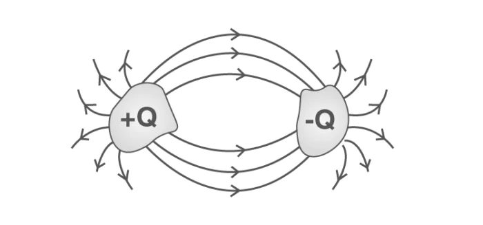
Diagram of a basic capacitor structure
Practical Uses of Capacitors
Capacitors serve multiple roles in electronic devices, including:
Storing electrical energy temporarily, similar to batteries.
Filtering out unwanted frequencies in signal processing.
Delaying voltage changes when used with resistors, aiding in timing circuits.
Acting as sensors in various applications.
Enhancing audio systems, such as those in vehicles.
Separating alternating current (AC) from direct current (DC) in circuits.
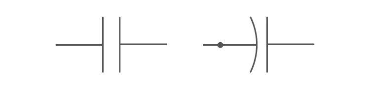
Standard circuit symbol for a capacitor
Charge Distribution in Capacitors
One plate of the capacitor carries a positive charge \(+Q\) at potential \(+V\), while the other holds an equal negative charge \(-Q\) at potential \(-V\). The net charge of the capacitor is zero, as the charges cancel each other out.
Capacitance: Definition, Calculation, and Influencing Factors
Defining Capacitance and Its Relationship with Charge and Voltage
The charge \(Q\) stored on a capacitor is directly proportional to the potential difference \(V\) across its plates, expressed as:
\[ Q = C V \]
Here, \(C\) is the capacitance, a constant that quantifies the capacitor's ability to store charge per unit voltage.
The unit of capacitance is the farad (F), and its dimensional formula is \(M^{-1}L^{-2}I^{2}T^{4}\).
Factors Affecting Capacitance
Several parameters influence the capacitance value:
The geometry and size of the conductive plates.
The nature of the insulating medium (dielectric) between the plates.
The presence of nearby conductive materials.
Calculating Capacitance for Different Capacitor Types
The general approach involves:
Assuming a charge \(Q\) on the plates.
Determining the electric field \(E\) between the plates.
Calculating the potential difference \(V\) from the electric field.
Using the relation \(C = \frac{Q}{V}\) to find capacitance.
Exploring Various Capacitor Designs and Their Capacitance Formulas
Parallel Plate Capacitor
This capacitor consists of two metal plates of area \(A\) separated by a small distance \(d\). The top plate carries charge \(+Q\), and the bottom plate carries \(-Q\), creating a potential difference \(V\).
Assuming negligible edge effects, the surface charge density is \(\sigma = \frac{Q}{A}\), and the electric field inside the capacitor is:
\[ E = \frac{\sigma}{\varepsilon_0} = \frac{Q}{A \varepsilon_0} \]
Since \(E = \frac{V}{d}\), the capacitance is:
\[ C = \frac{Q}{V} = \frac{A \varepsilon_0}{d} \]
For a dielectric medium with dielectric constant \(k\), the capacitance becomes:
\[ C = \frac{k A \varepsilon_0}{d} \]
Here, \(\varepsilon_0 = 8.85 \times 10^{-12} \text{ C}^2/\text{N m}^2\) is the permittivity of free space.
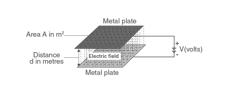
Structure of a parallel plate capacitor
Spherical Capacitor
A spherical capacitor consists of two concentric spherical shells with radii \(a\) (inner) and \(b\) (outer). The inner shell holds charge \(+Q\), and the outer shell holds \(-Q\).
The potential difference between the shells is:
\[ V = \frac{Q}{4 \pi \varepsilon_0 k} \left( \frac{1}{a} - \frac{1}{b} \right) = \frac{Q}{4 \pi \varepsilon_0 k} \frac{b - a}{a b} \]
Thus, the capacitance is:
\[ C = \frac{Q}{V} = 4 \pi \varepsilon_0 k \frac{a b}{b - a} \]
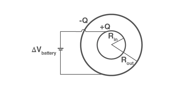
Spherical capacitor configuration
Cylindrical Capacitor
This capacitor features a solid inner cylinder of radius \(a\) surrounded by a cylindrical shell of radius \(b\), both of length \(L\) (with \(L \gg b - a\) to minimize edge effects). The inner cylinder carries charge \(+Q\), and the outer shell carries \(-Q\).
Using Gauss's law, the electric field at a distance \(r\) from the axis is:
\[ E = \frac{Q}{2 \pi \varepsilon_0 r L} = \frac{\lambda}{2 \pi \varepsilon_0 r} \]
where \(\lambda = \frac{Q}{L}\) is the linear charge density.
The potential difference between the cylinders is:
\[ \Delta V = V_b - V_a = -\int_a^b E \, dr = \frac{\lambda}{2 \pi \varepsilon_0} \ln \left( \frac{b}{a} \right) \]
Therefore, the capacitance is:
\[ C = \frac{Q}{|\Delta V|} = \frac{2 \pi \varepsilon_0 L}{\ln(b/a)} \]
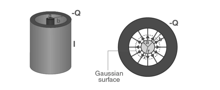
Cylindrical capacitor setup
Worked Examples on Capacitors and Capacitance
Example 1: Capacitance of a Conducting Sphere
Problem: Calculate the capacitance of a conducting sphere with radius \(R = 0.05 \text{ m}\).
Solution:
The electric field outside the sphere at distance \(r\) is:
\[ E = \frac{k Q}{r^2} \]
Using the relation \(-\frac{dV}{dr} = E\), integrate from infinity to \(R\):
\[ V = -\int_\infty^R E \, dr = k Q \left[ -\frac{1}{r} \right]_\infty^R = \frac{k Q}{R} \]
Capacitance is:
\[ C = \frac{Q}{V} = \frac{R}{k} = 4 \pi \varepsilon_0 R \]
Substituting values:
\[ C = 4 \pi \times 8.85 \times 10^{-12} \times 0.05 = 5.56 \times 10^{-12} \text{ F} \]
Example 2: Parallel Plate Capacitor Characteristics
Problem: A parallel plate capacitor has plates of area \(0.15 \text{ m}^2\) separated by \(2 \text{ mm}\). It is connected to a \(60 \text{ V}\) battery. Find:
Capacitance
Charge on each plate
Electric field between plates
Effect on these values if the plates are separated to \(4 \text{ mm}\) after disconnecting the battery
Solution:
Capacitance:
\[ C = \frac{\varepsilon_0 A}{d} = \frac{8.85 \times 10^{-12} \times 0.15}{0.002} = 6.64 \times 10^{-10} \text{ F} \]
Charge on each plate:
\[ Q = C V = 6.64 \times 10^{-10} \times 60 = 3.98 \times 10^{-8} \text{ C} \]
Electric field between plates:
\[ E = \frac{V}{d} = \frac{60}{0.002} = 3 \times 10^{4} \text{ V/m} \]
After disconnecting the battery and doubling the plate separation to \(4 \text{ mm}\):
Charge remains constant: \(Q = 3.98 \times 10^{-8} \text{ C}\)
New capacitance:
\[ C' = \frac{\varepsilon_0 A}{0.004} = 3.32 \times 10^{-10} \text{ F} \]
New potential difference:
\[ V' = \frac{Q}{C'} = \frac{3.98 \times 10^{-8}}{3.32 \times 10^{-10}} = 120 \text{ V} \]
Electric field remains the same:
\[ E' = \frac{V'}{0.004} = 3 \times 10^{4} \text{ V/m} \]
Example 3: Battery Voltage from Stored Charge
Problem: A parallel plate capacitor with plate area \(4.0 \text{ cm}^2\) and plate separation \(3 \text{ mm}\) stores a charge of \(5.0 \text{ pC}\). Calculate the voltage of the battery connected.
Solution:
Convert area to square meters:
\[ A = 4.0 \times 10^{-4} \text{ m}^2 \]
Capacitance:
\[ C = \frac{\varepsilon_0 A}{d} = \frac{8.85 \times 10^{-12} \times 4.0 \times 10^{-4}}{3 \times 10^{-3}} = 1.18 \times 10^{-12} \text{ F} \]
Voltage:
\[ V = \frac{Q}{C} = \frac{5.0 \times 10^{-12}}{1.18 \times 10^{-12}} = 4.24 \text{ V} \]
Dielectrics: Properties and Influence on Capacitance
What Are Dielectrics?
Dielectrics are insulating materials that lack free electrons but exhibit microscopic charge displacement when subjected to an electric field. Introducing a dielectric between capacitor plates increases the capacitance by reducing the effective electric field.
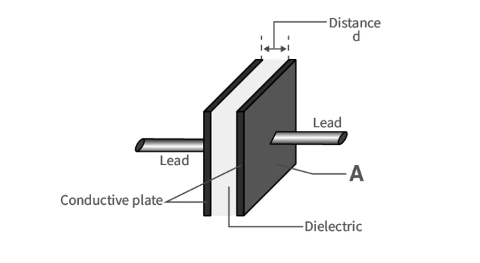
Dielectric material placed between capacitor plates
Polar and Non-Polar Dielectrics
Atoms consist of a positively charged nucleus surrounded by electrons. If the centers of positive and negative charges do not coincide, the molecule has a permanent dipole moment and is called polar. Polar dielectrics align their dipoles with an external electric field.
Non-polar molecules have coinciding charge centers but develop induced dipoles when exposed to an electric field.
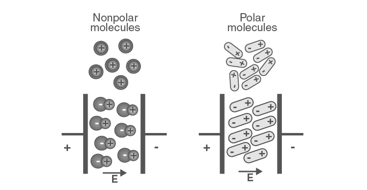
Polar and non-polar molecules under electric field
Polarization of Dielectric Slabs
Polarization refers to the induction of dipole moments within a dielectric material, resulting in surface charges and an internal electric field opposing the applied field. The polarization vector \(\overrightarrow{p}\) represents the dipole moment per unit volume.
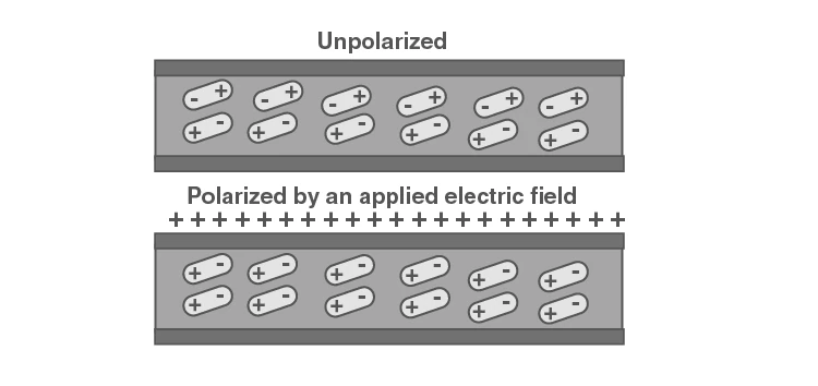
Polarization effect in a dielectric slab
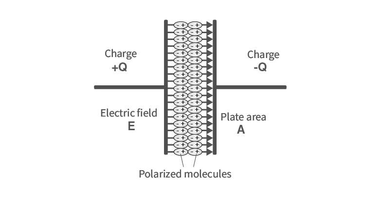
Dipole alignment within dielectric under electric field
Dielectric Constant and Its Effect
The resultant electric field \(\overrightarrow{E}\) inside a dielectric is the vector sum of the external field \(\overrightarrow{E_0}\) and the induced polarization field \(\overrightarrow{E_p}\):
\[ \overrightarrow{E} = \overrightarrow{E_0} + \overrightarrow{E_p} \]
Since \(\overrightarrow{E_p}\) opposes \(\overrightarrow{E_0}\), the net field magnitude is reduced:
\[ \overrightarrow{E} = \frac{\overrightarrow{E_0}}{K} \]
Here, \(K\) is the dielectric constant or relative permittivity. For vacuum, \(K=1\).
Electric field modification due to dielectric polarization
Capacitance with Dielectric Slabs in Series
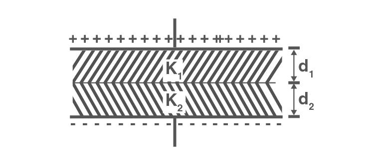
When a capacitor contains two dielectric slabs of thicknesses \(d_1\) and \(d_2\) with dielectric constants \(k_1\) and \(k_2\), the equivalent capacitance is:
\[ \frac{1}{C} = \frac{d_1}{k_1 \varepsilon_0 A} + \frac{d_2}{k_2 \varepsilon_0 A} \]
Or equivalently:
\[ C = \frac{\varepsilon_0 A}{\frac{d_1}{k_1} + \frac{d_2}{k_2}} \]
Capacitor with dielectric slabs arranged in series
Capacitance with Dielectric Slabs in Parallel
If two dielectric slabs of equal thickness \(d\) but different dielectric constants \(k_1\) and \(k_2\) and areas \(A_1\) and \(A_2\) are placed side by side between capacitor plates, the total capacitance is the sum of individual capacitances:
\[ C = \frac{k_1 \varepsilon_0 A_1}{d} + \frac{k_2 \varepsilon_0 A_2}{d} = \frac{\varepsilon_0}{d} (k_1 A_1 + k_2 A_2) \]
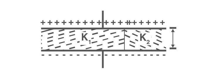
Capacitor with dielectric slabs arranged in parallel
Effect of Partial Dielectric Filling
When a dielectric slab of thickness \(t\) and dielectric constant \(k\) partially fills the space between plates separated by distance \(d\), the equivalent capacitance is:
\[ C = \frac{\varepsilon_0 A}{\frac{t}{k} + (d - t)} \]
If the slab is metallic, the capacitance becomes:
\[ C = \frac{\varepsilon_0 A}{d - t} \]
Practice Problems on Capacitors and Dielectrics
Problem 1: Equivalent Capacitance with Dielectrics
Three capacitors, each of \(12 \mu F\), are connected as shown. Two capacitors are filled with dielectrics having dielectric constants \(2\) and \(2.5\) respectively. Calculate the equivalent capacitance.
Solution:
Capacitances after dielectric insertion:
\[ C_1 = 12 \mu F, \quad C_2 = 2 \times 12 = 24 \mu F, \quad C_3 = 2.5 \times 12 = 30 \mu F \]
Equivalent capacitance (assuming series and parallel as per circuit):
\[ C_{eff} = \frac{12 \times 24}{12 + 24} + 30 = 38 \mu F \]
Problem 2: Capacitance of Composite Dielectric System
Calculate the equivalent capacitance of a capacitor with two dielectric slabs of thicknesses \(d/3\) and \(2d/3\), dielectric constants \(2\) and \(3\), and plate area \(L^2\).
Solution:
Capacitance of first slab:
\[ C_1 = \frac{2 \varepsilon_0 L \times \frac{L}{3}}{\frac{d}{3}} = \frac{6 \varepsilon_0 L^2}{d} \]
Capacitance of second slab:
\[ C_2 = \frac{3 \varepsilon_0 L \times \frac{L}{3}}{\frac{2d}{3}} = \frac{3 \varepsilon_0 L^2}{2 d} \]
Equivalent capacitance in series:
\[ \frac{1}{C_{left}} = \frac{1}{C_1} + \frac{1}{C_2} = \frac{d}{6 \varepsilon_0 L^2} + \frac{2 d}{3 \varepsilon_0 L^2} = \frac{5 d}{6 \varepsilon_0 L^2} \]
\[ C_{left} = \frac{6 \varepsilon_0 L^2}{5 d} \]
Capacitance of right slab:
\[ C_{right} = \frac{4 \varepsilon_0 L \times \frac{2L}{3}}{d} = \frac{8 \varepsilon_0 L^2}{3 d} \]
Total equivalent capacitance (parallel):
\[ C_{eq} = C_{left} + C_{right} = \frac{6 \varepsilon_0 L^2}{5 d} + \frac{8 \varepsilon_0 L^2}{3 d} = \frac{58 \varepsilon_0 L^2}{15 d} \]
Problem 3: Series and Parallel Capacitor Connection
Two capacitors \(C_1 = 15 F\) and \(C_2 = 5 F\) are connected to a \(50 V\) battery. Find the effective capacitance and voltage across each capacitor when connected in series and parallel.
Solution:
Series connection:
\[ \frac{1}{C} = \frac{1}{15} + \frac{1}{5} = \frac{1}{15} + \frac{3}{15} = \frac{4}{15} \]
\[ C = \frac{15}{4} = 3.75 F \]
Charge on capacitors:
\[ Q = C V = 3.75 \times 50 = 187.5 C \]
Voltage across \(C_1\):
\[ V_1 = \frac{Q}{C_1} = \frac{187.5}{15} = 12.5 V \]
Voltage across \(C_2\):
\[ V_2 = \frac{Q}{C_2} = \frac{187.5}{5} = 37.5 V \]
Parallel connection:
\[ C = C_1 + C_2 = 15 + 5 = 20 F \]
Voltage across each capacitor is the same as battery voltage:
\[ V = 50 V \]
Quick Reference: Capacitor Formulas and Constants
Concept | Formula | Notes |
|---|---|---|
Capacitance (general) | \(C = \frac{Q}{V}\) | Charge per unit voltage |
Parallel Plate Capacitor | \(C = \frac{k \varepsilon_0 A}{d}\) | \(k\) is dielectric constant, \(d\) plate separation |
Spherical Capacitor | \(C = 4 \pi \varepsilon_0 k \frac{a b}{b - a}\) | \(a,b\) are radii of inner and outer spheres |
Cylindrical Capacitor | \(C = \frac{2 \pi \varepsilon_0 L}{\ln(b/a)}\) | \(a,b\) radii, \(L\) length |
Dielectric Slabs in Series | \(\frac{1}{C} = \frac{d_1}{k_1 \varepsilon_0 A} + \frac{d_2}{k_2 \varepsilon_0 A}\) | Two dielectrics with thicknesses \(d_1, d_2\) |
Dielectric Slabs in Parallel | \(C = \frac{\varepsilon_0}{d} (k_1 A_1 + k_2 A_2)\) | Two dielectrics side by side |
Permittivity of Free Space | \(\varepsilon_0 = 8.85 \times 10^{-12} \text{ C}^2/\text{N m}^2\) | Fundamental constant |
Dielectric Constant | \(K = \frac{E_0}{E}\) | Ratio of external to resultant electric field |
Glossary of Key Terms
Term | Definition |
|---|---|
Capacitor | A device that stores electrical energy in an electric field between two conductors. |
Capacitance | The ability of a capacitor to store charge per unit voltage, measured in farads. |
Dielectric | An insulating material placed between capacitor plates to increase capacitance. |
Dielectric Constant (K) | A measure of a material's ability to reduce the electric field within it. |
Electric Field (E) | The force per unit charge exerted on a charged particle in space. |
Polar Molecule | A molecule with a permanent electric dipole moment due to uneven charge distribution. |
Non-Polar Molecule | A molecule with no permanent dipole moment but can have induced dipoles. |
Polarization | The alignment of dipoles within a dielectric material under an electric field. |
Permittivity of Free Space (\(\varepsilon_0\)) | A constant representing the ability of vacuum to permit electric field lines. |
Potential Difference (V) | The work done to move a unit charge between two points in an electric field. |
Frequently Asked Questions (FAQs)
What is the definition of capacitance?
Capacitance is the ratio of the magnitude of charge stored on one conductor to the potential difference between the conductors.
How can the capacitance of a parallel plate capacitor be increased?
By increasing the plate area, decreasing the distance between plates, or inserting a dielectric material with a higher dielectric constant.
Does the capacitance change if the charge on the capacitor doubles?
No, capacitance is independent of the charge and depends only on the physical characteristics of the capacitor.
What happens to the charge on a capacitor if the voltage across it doubles?
The charge stored on the capacitor also doubles, as \(Q = CV\).
Why does inserting a dielectric increase capacitance?
The dielectric reduces the effective electric field inside the capacitor, allowing more charge to be stored for the same voltage.