Understanding Series and Parallel Resistor Networks
Fundamentals of Electrical Circuit Components
Key Elements in an Electric Circuit
An electric circuit consists of several essential parts including conductors (usually copper wires), a power source, resistors, loads, and switches. The circuit forms a closed loop, allowing current to flow from the power source through various components and back. Conductors provide the path for current, while switches control the connectivity by opening or closing the circuit. Resistors serve to regulate the current flow by providing resistance, consuming electrical energy without generating it. Loads such as bulbs or fans convert electrical energy into other usable forms like light or mechanical energy.
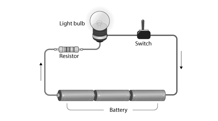
Illustration of a Basic Electrical Circuit
Example: Identify the role of each component in a simple circuit containing a battery, a switch, a resistor, and a bulb.
Solution:
Battery: Provides the electrical energy.
Switch: Controls the flow of current by opening or closing the circuit.
Resistor: Limits the current to protect components.
Bulb (Load): Converts electrical energy into light.
Why Combine Resistors in Circuits?
Purpose of Resistor Networks
In practical circuits, resistors are rarely used alone. Instead, they are connected in various arrangements to achieve desired electrical characteristics. Combining resistors in series or parallel allows engineers to tailor the total resistance, control current flow, and manage voltage distribution. Complex circuits often feature mixed resistor networks, where some resistors are in series and others in parallel, forming intricate loops. Understanding how to calculate the overall resistance in these combinations is crucial for designing and analyzing circuits effectively.
Example: Explain why a combination of series and parallel resistors might be used in a household electrical system.
Answer:
To ensure different appliances receive appropriate voltage and current.
To protect devices by limiting current through specific paths.
To allow independent operation of devices without affecting others.
Characteristics of Resistors Connected in Series
Understanding Series Resistor Arrangements
When resistors are connected end-to-end so that the same current passes sequentially through each, they are said to be in series. In this setup, the current remains constant across all resistors, but the voltage drop varies depending on each resistor's value. A key feature of series circuits is that if any resistor fails or is disconnected, the entire circuit is interrupted. Series circuits are simpler to construct but less flexible compared to parallel arrangements.

Visual Representation of Resistors in Series
The total resistance \( R_{\text{total}} \) in a series circuit is the sum of all individual resistances:
\[ R_{\text{total}} = R_1 + R_2 + \cdots + R_n \]
Example: Calculate the total resistance when three resistors of 150 Ω, 250 Ω, and 100 Ω are connected in series.
Solution:
Given: \( R_1 = 150 \, \Omega \), \( R_2 = 250 \, \Omega \), \( R_3 = 100 \, \Omega \)
Total resistance is:
\[ R_{\text{total}} = 150 + 250 + 100 = 500 \, \Omega \]
Thus, the combined resistance of the series circuit is \( 500 \, \Omega \).
Properties of Resistors Connected in Parallel
Exploring Parallel Resistor Configurations
Resistors are in parallel when their terminals are connected to the same two points, resulting in the same voltage across each resistor. Unlike series circuits, the current divides among the parallel branches according to each resistor's value. This arrangement allows individual components to be disconnected without interrupting the entire circuit. Calculating total resistance in parallel requires summing the reciprocals of each resistor's resistance.

Illustration of Resistors Connected in Parallel
The formula for total resistance \( R_{\text{total}} \) in a parallel circuit is:
\[ \frac{1}{R_{\text{total}}} = \frac{1}{R_1} + \frac{1}{R_2} + \cdots + \frac{1}{R_n} \]
Example: Find the total resistance of two resistors, 120 Ω and 80 Ω, connected in parallel.
Solution:
Given: \( R_1 = 120 \, \Omega \), \( R_2 = 80 \, \Omega \)
Calculate reciprocal of total resistance:
\[ \frac{1}{R_{\text{total}}} = \frac{1}{120} + \frac{1}{80} = \frac{2}{240} + \frac{3}{240} = \frac{5}{240} \]
Therefore, total resistance is:
\[ R_{\text{total}} = \frac{240}{5} = 48 \, \Omega \]
The combined resistance of the parallel circuit is \( 48 \, \Omega \).
Concise Overview of Resistor Combinations
Aspect | Series Connection | Parallel Connection |
|---|---|---|
Current | Same through all resistors | Divides among branches |
Voltage | Varies across each resistor | Same across all resistors |
Total Resistance | Sum of resistances: \( R_{\text{total}} = \sum R_i \) | Reciprocal sum: \( \frac{1}{R_{\text{total}}} = \sum \frac{1}{R_i} \) |
Effect of a Fault | Entire circuit stops if one resistor fails | Other branches continue to operate |
Complex Networks | Can be combined with parallel for mixed circuits | Can be combined with series for mixed circuits |
Essential Terms and Definitions
Term | Definition |
|---|---|
Resistor | A component that opposes electric current, providing resistance. |
Series Circuit | A circuit where components are connected end-to-end, sharing the same current. |
Parallel Circuit | A circuit where components share the same voltage across their terminals. |
Total Resistance | The equivalent resistance of combined resistors in a circuit. |
Load | A device that consumes electrical energy and converts it to other forms. |
Conductor | A material that allows electric current to flow easily, e.g., copper wire. |
Switch | A device used to open or close an electric circuit. |
Voltage | The electric potential difference between two points. |
Current | The flow of electric charge through a conductor. |
Mixed Resistor Circuit | A circuit containing both series and parallel resistor connections. |
Frequently Asked Questions
What is the primary role of a resistor in a circuit?
A resistor controls and limits the flow of electric current within a circuit.
How do you calculate total resistance in a series circuit?
Add all individual resistances: \( R_{\text{total}} = R_1 + R_2 + \cdots + R_n \).
What formula is used to find total resistance in parallel?
Use the reciprocal sum: \(\frac{1}{R_{\text{total}}} = \frac{1}{R_1} + \frac{1}{R_2} + \cdots + \frac{1}{R_n}\).
Can a resistor generate electrical power?
No, a resistor is a passive component that only consumes power, it does not generate it.
What happens if one resistor in a series circuit breaks?
The entire circuit stops functioning because the current path is interrupted.