Fundamentals of Electric Circuits and Their Components
Understanding the Basics of Electric Circuits
Concept and Flow of Electric Current
An electric circuit is a closed path that allows electrons to move continuously through various electrical components. This path is typically formed by connecting wires and powered by a source such as a battery. The point where electrons begin their journey is called the source, and the point where they return is known as the return path. For current to flow, the circuit must be complete without any breaks.
Consider a simple setup involving an electric bulb, connecting wires, electrical tape, and a battery. When one wire is connected from the bulb to the battery, the bulb remains off. However, once the circuit is closed by connecting the other wire to the battery, the bulb lights up, demonstrating the necessity of a complete circuit for current flow.
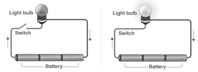
Diagram showing a basic electric circuit with a bulb and battery
Electric circuits can range from simple loops to complex networks found in devices like televisions. Safety is paramount when dealing with electricity, as improper handling can lead to severe hazards including fire and electric shock. For instance, electrical wires and sockets should be insulated and kept out of children's reach. While small batteries typically have voltages up to 12 volts, transformers can have voltages as high as 11,000 volts, which are extremely dangerous.
Faulty wiring can cause fires, and water should never be used to extinguish electrical fires; specialized extinguishers are required. Additionally, batteries should never have their terminals connected directly without a load, as this can cause rapid chemical reactions leading to explosions.
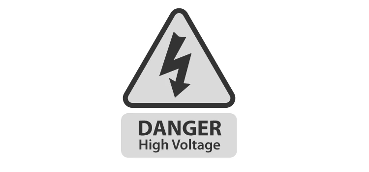
Warning signs indicating electrical hazards on equipment
Example Problem
Problem: A simple circuit consists of a 9 V battery connected to a bulb through copper wires. Explain why the bulb does not light up if the circuit is incomplete and what happens when the circuit is closed.
Solution:
When the circuit is incomplete, electrons cannot flow through the bulb because the path is broken, so the bulb remains off.
Once the circuit is closed by connecting the free end of the wire to the battery, electrons flow from the negative terminal through the bulb to the positive terminal.
This flow of electrons causes the filament in the bulb to heat up and emit light, making the bulb glow.
Symbols Representing Circuit Components
Common Electrical Symbols and Their Significance
In circuit diagrams, each electrical component is represented by a specific symbol to simplify the understanding and construction of circuits. These symbols help in visualizing the arrangement and connections without the need for physical components.
Some basic symbols include:
Cell: Depicted as a pair of parallel lines, representing the power source.
Load (Resistor): Shown as a zigzag line or a bulb symbol, indicating a device that consumes electrical energy.
Conductors: Straight lines representing wires that connect components.
Switch: A break in the line that can be opened or closed to control the flow of current.
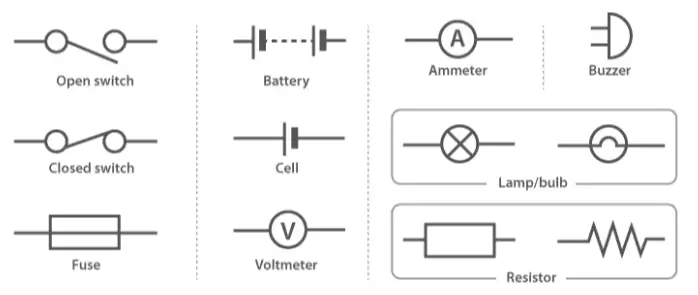
Standard symbols used in electric circuit diagrams
Example Problem
Problem: Identify the components represented by the following symbols in a circuit diagram: a pair of parallel lines, a zigzag line, and a break in the line.
Solution:
The pair of parallel lines represents a cell or power source.
The zigzag line indicates a resistor or load, such as a bulb.
The break in the line symbolizes a switch, which can open or close the circuit.
Constructing and Analyzing Simple Electric Circuits
Components and Their Roles in a Basic Circuit
A simple electric circuit consists of four main parts: the power source (cell), conductors (wires), a switch, and a load (such as a bulb). The cell provides the electrical energy, conductors allow current to flow, the switch controls the circuit's continuity, and the load converts electrical energy into other forms like light.
Conductors are usually copper wires without insulation at the ends to allow connections. The switch creates a gap in the circuit that can be opened or closed to stop or allow current flow.
Illustration of a simple electric circuit with labeled components
Example Problem
Problem: Describe the function of each component in a simple circuit consisting of a battery, wires, a switch, and a bulb.
Solution:
Battery (Cell): Supplies electrical energy to the circuit.
Wires (Conductors): Provide a path for current to flow between components.
Switch: Opens or closes the circuit to control the flow of current.
Bulb (Load): Converts electrical energy into light when current passes through it.
Essential Formulas in Electric Circuit Analysis
Key Relationships and Calculations
Several fundamental formulas are used to analyze electric circuits. Understanding these helps in calculating current, resistance, power, and energy in circuits.
Current (I): The rate of flow of charge, given by \( I = \frac{Q}{t} \), where \( Q \) is the charge in coulombs and \( t \) is the time in seconds.
Resistance (R): Depends on the resistivity \( \rho \), length \( L \), and cross-sectional area \( A \) of the wire: \[ R = \rho \frac{L}{A} \]
Power (P): The rate at which electrical energy is consumed or produced: \[ P = \frac{\Delta E}{t} \] where \( \Delta E \) is the energy change and \( t \) is time.
Total Resistance in Series (R_{eq}): Sum of individual resistances: \[ R_{eq} = R_1 + R_2 + \cdots \]
Total Resistance in Parallel (R_{eq}): Reciprocal of the sum of reciprocals: \[ \frac{1}{R_{eq}} = \frac{1}{R_1} + \frac{1}{R_2} + \cdots \]
Formulas commonly used in electric circuit calculations
Example Problem
Problem: A wire of length 2 m and cross-sectional area \( 1 \times 10^{-6} \text{ m}^2 \) has a resistivity of \( 1.7 \times 10^{-8} \Omega \text{m} \). Calculate its resistance.
Solution:
Using the formula for resistance:
\[ R = \rho \frac{L}{A} = (1.7 \times 10^{-8}) \times \frac{2}{1 \times 10^{-6}} = 3.4 \times 10^{-2} \Omega \]
Therefore, the resistance of the wire is \( 0.034 \Omega \).
Quick Reference: Key Electric Circuit Concepts
Term | Definition | Formula / Symbol |
|---|---|---|
Electric Current (I) | Flow of electric charge per unit time | \( I = \frac{Q}{t} \) |
Charge (Q) | Quantity of electricity carried | Measured in coulombs (C) |
Resistance (R) | Opposition to current flow | \( R = \rho \frac{L}{A} \) |
Resistivity (\( \rho \)) | Material property affecting resistance | Units: \( \Omega \text{m} \) |
Power (P) | Rate of energy consumption | \( P = \frac{\Delta E}{t} \) |
Voltage (\( \Delta V \)) | Electric potential difference | Measured in volts (V) |
Load | Component consuming electrical energy | Often a bulb or resistor |
Switch | Controls circuit continuity | Open or closed state |
Series Resistance | Total resistance in series connection | \( R_{eq} = R_1 + R_2 + \cdots \) |
Parallel Resistance | Total resistance in parallel connection | \( \frac{1}{R_{eq}} = \frac{1}{R_1} + \frac{1}{R_2} + \cdots \) |
Glossary of Electric Circuit Terms
Term | Meaning |
|---|---|
Electric Circuit | A closed path allowing electric current to flow |
Current (I) | Rate of flow of electric charge |
Charge (Q) | Quantity of electricity carried by electrons |
Resistance (R) | Measure of opposition to current flow |
Resistivity (\( \rho \)) | Intrinsic property of a material affecting resistance |
Voltage (\( \Delta V \)) | Electric potential difference between two points |
Power (P) | Rate at which electrical energy is used or produced |
Load | Device that consumes electrical energy |
Switch | Component that opens or closes a circuit |
Conductors | Materials that allow electric current to pass through |
Frequently Asked Questions (FAQs)
What defines an electric circuit?
An electric circuit is a continuous closed loop that allows electric current to flow through connected components.
What is the role of a switch in a circuit?
A switch controls the circuit by opening (breaking) or closing (completing) the path for current flow.
How is electric current calculated?
Electric current is calculated using the formula \( I = \frac{Q}{t} \), where \( Q \) is the charge and \( t \) is the time.
When is a circuit considered complete?
A circuit is complete when there is an uninterrupted path from the positive terminal of the power source through the components back to the negative terminal.
What formula is used to determine electrical power?
Power is given by \( P = \frac{\Delta E}{t} \), where \( \Delta E \) is the energy transferred and \( t \) is the time taken.